VisionPro provides a set of 3D vision tools that let you directly obtain information about plane estimation, height calculation, and volume measurement from 3D range images.
Many other vision tools can accept 3D images, such as the PMAlign and OCRMax tools. See the topic Vision Tools and Supported Image Types for a table of all vision tools and the image types they support.
If the vision tool you need does not accept 3D images, your vision application must do the following:
- Select the desired coordinate space (calibrated millimeter space or pixel space).
- Fill any missing pixels (or decide to use the visible pixel mask).
- Convert the range image to a 16-bit greyscale image.
- Map the 16-bit greyscal image to an 8-bit greyscale image of the vision tool does not support 16-bit images.
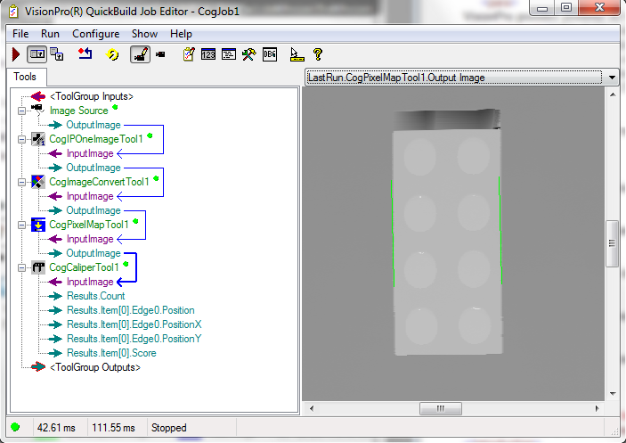
For example, the following figure shows the steps involved in converting a 3D image into an 8-bit image to be analyzed by a Caliper tool.
This topic contains the following sections.
Whenever you acquire a range image from a Cognex 3D displacement sensor, the acquisition system automatically constructs a calibrated 3D space that lets you map range image pixels (x,y,z) into physical coordinates:
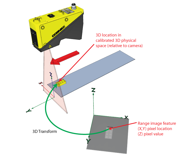
The acquisition system also creates a corresponding calibrated 2D space that maps between x,y coordinates in the range image and a calibrated 2D space created by the camera. The calibrated 2D space corresponds to the plane in Sensor3D space with a Z-value of 0.
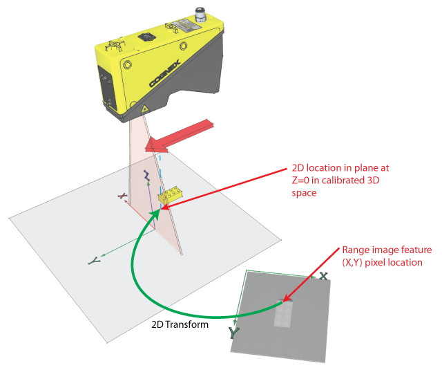
The acquisition system always adds this calibrated 2D space to the 2D coordinate space tree associated with the acquired image. By default, the space is named "Sensor2D", and it is set as the selected space for the acquired images. You can specify a different name using the Calibrate tab of the Image Source or the CalibratedSpaceName2D property, and you can specify that the selected space be set to "@" instead of the calibrated space using the SelectCalibratedSpace2D property.
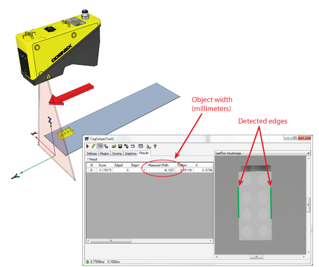
If Sensor2D is the selected space, all vision tool input parameters and regions, and all vision tool results are interpreted in calibrated millimeter space, relative to the camera. The following image shows how a Caliper tool can be used to return the width of an object in millimeters:
Whenever you use a 2D vision tool on an image with the Sensor2D space selected, the feature positions and other information are reported at their projected position in the Z=0 plane of Sensor3D space.
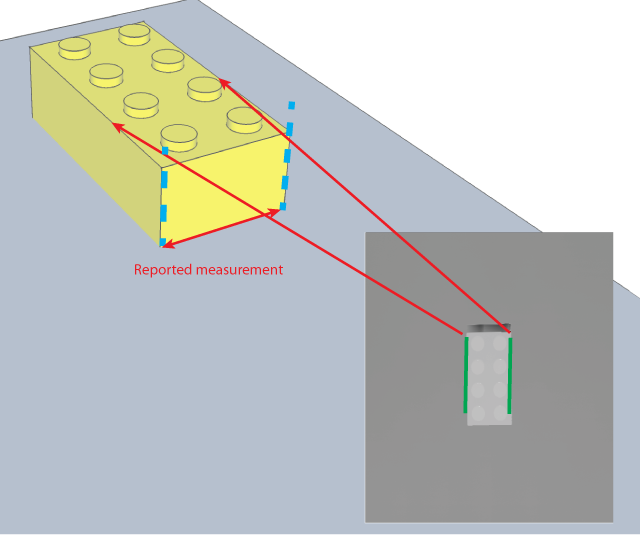
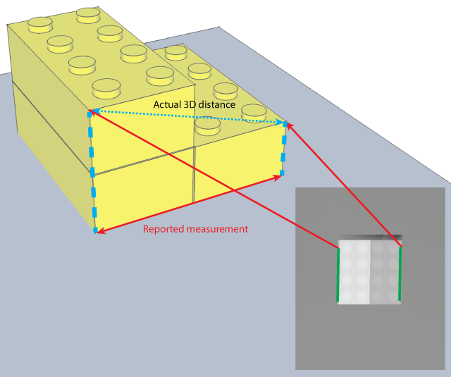
In general, this information corresponds with a high degree of accuracy to the actual physical position of the features. However, whenever you compute measures (such as distance or area) using multiple features in a range image, all of the computed measures assume that all of the features are coplanar with each other in a plane that is perpendicular to the Sensor3D z-axis. In cases where this is not true, the reported measurements will be accurate, but they may not be the actual 3D measurement.
The following figure shows how measurements may be affected when multiple features that are not coplanar are measured:
Most range images include missing pixels (pixels where no height data is available). These pixels are indicated by a visible pixel mask that is part of the CogImage16Range image. In almost all cases, you should use the missing pixel operator of the One Image Image Processing Tool to fill missing pixels with interpolated or synthetic data.
You can use the GetMaskData method to obtain a mask that indicates the locations of the missing pixels in the image; some 2D vision tools can use this mask, but others cannot. The missing pixel operator will create an image that works with all 2D vision tools.
Use the Pixel From Range option of the Image Convert Tool to convert a CogImage16Range image into a CogImage16Grey image, as necessary.
The topic Vision Tools and Supported Image Types lists all the vision tools that can accept 16-bit greyscale images.
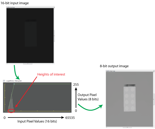
The simplest method for converting the 16-bit image to an 8-bit image is to use the PixelMap Tool.
The basic operation of the PixelMap tool is to map a selected range of pixel values from the 16-bit image into the full range of pixel values in the 8-bit image. Since there are 65,536 possible values in a 16-bit image but only 256 possible pixel values in an 8-bit image, the mapping operation will result in the loss of information from the range image. (However, for example, using the default acquisition parameters for a DS1000 series sensor, the entire working distance of the sensor can be encoded using the values 1 to 16,500, and in most cases the only a portion of the working distance is used for a particular measurement.)
When considering how to map the 65536 possible pixel values in a 16-bit image into the 256 possible values in an 8-bit image, keep the following points in mind:
- You should define your pixel mapping to maximize the contrast of your features of interest in the output image. This is done by mapping the smallest range of pixel values in the input range that encompass the lowest and highest features in the input range image to the full 0-255 range of pixel values in the output image.
- If the range images acquired by your application have the features of interest at known heights from image to image, you can use fixed values for the lower and upper mapping points. If the features of interest are at varying heights, then you can use the Histogram Tool to estimate the upper and lower mapping points.
The following figure shows the effect of a typical mapping operation: