This topic contains the following sections.
This topic describes the coordinate spaces associated with range images acquired from DS900 and DS1000 series sensors, in particular from the DS1100 sensor. It also discusses how range image parameters associated with these coordinate spaces influence range image generation.
For the theory of range images, see the Working with 3D Range Images topic. For information on setting up acquisition with your displacement sensor quickly, see the Getting Started topic. For detailed information on range image acquisition, see the Acquiring Images from a DS900 Series Sensor and Acquiring Images from a DS1000 Series Sensor topics. For hardware-related information (such as mounting and physical product features) and further product details, see the DS900 Quick Reference Guide and DS1000 Quick Reference Guide, as well as the DS1000 Technical Reference Manual.
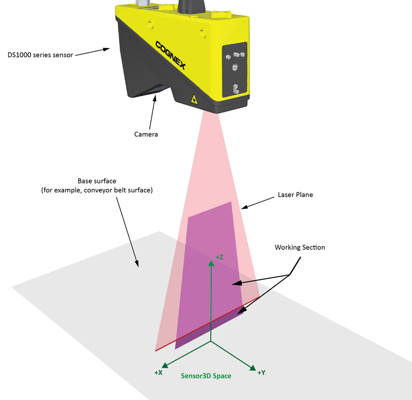
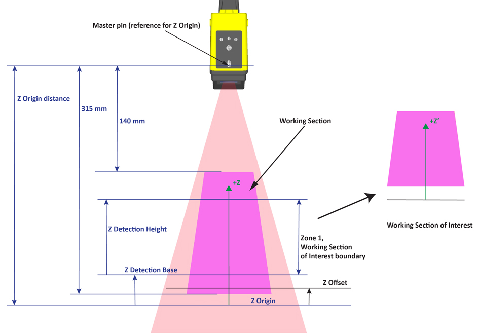
Information appearing in range images is expressed by default in the physical Sensor3D Space and the 3D Pixel Space, both placed at the time when range image acquisition starts. The Working Section of the displacement sensor is defined as the cross-section of the laser plane and what the camera in the sensor can see. In the images below, part of the Working Section is above the base surface on which the object under inspection travels, and part of it is below the base surface.
The following figure shows the Sensor3D Space, which is a right-handed coordinate space.
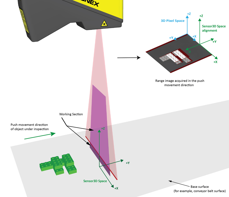
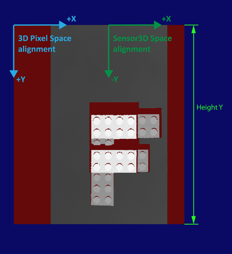
The following figure shows acquisition in the push direction, the acquired range image, and the alignment of coordinate spaces relative to the range image:
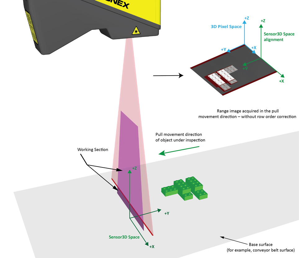
The following figure shows acquisition in the pull direction, the acquired range image, and the alignment of coordinate spaces relative to the range image:
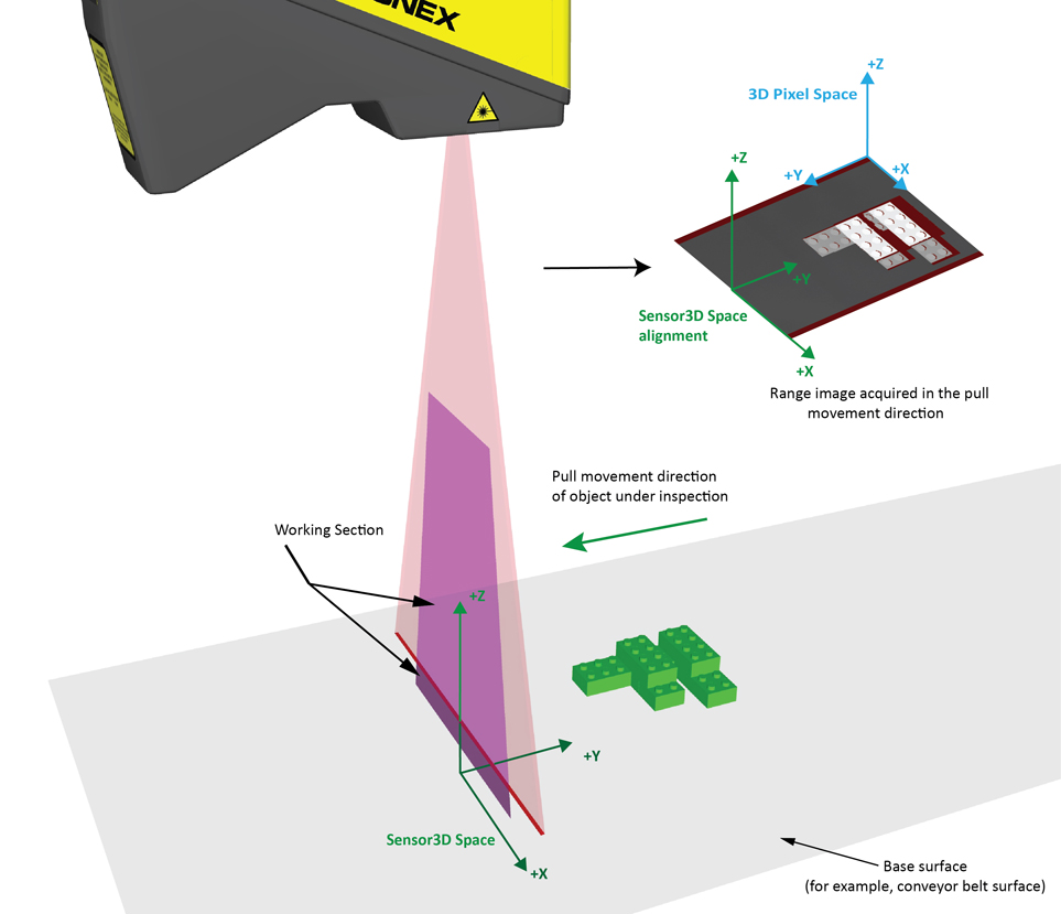
The Sensor3D Space is bound to the range image, and moves with the inspected area passing through the Working Section; i.e. it moves together with the objects under inspection, in the direction of their motion.
The Sensor2D Space corresponds to the plane in the Sensor3D Space with a Z-value of 0. By default, this space is set as the selected space for the acquired images. You can use it with applications using 2D vision tools that require image features to be specified in real physical units (mm) instead of pixels. For more information, see the Using 2D Vision Tools with Range Images topic.
If you want information to be expressed in a different physical coordinate space than the Sensor3D space, you can use the 3D coordinate space tree contained in the range image.
The following figure shows the acquisition properties you can set related to the Z axis of the Sensor3D Space:
For the DS900 models, which have no master pin, the face where the laser beam exits the unit is used as a mechanical reference plane. The mechanical drawing depicts the locaion of the Field of View (FOV) relative to the mechanical reference plane. The VisionPro range image uses unsigned 16-bit pixels to represent heights, where the height at the midpoint of the FOV is represented by the value 32768. This value is converted to physical units (in millimeters) in the Sensor3D coordinate space by a scale factor which differs for the different units. Heghts in Sensor3D coordinates therefore are relative to an origin which is a distance FOVcenter + (scaleFactor * 32768) from the mechanical reference plane.
For the DS1100 model of the DS1000 series sensors, the distance is 350 mm.
By default, Zone 1 is the height range in which heights will be detected (in mm); the ZDetectionBase and ZDetectionHeight parameters define this height range. The intersection of this height range and the Working Section defines the Working Section of Interest, which is typically the subregion of the Working Section. The overlap of the Working Section and the Working Section of Interest defines the region in which bright stripe curve finding is performed. Pixels beyond this region are ignored most of the time. Sometimes the acquired range image may include range pixels with heights slightly above or below the height limits of the Working Section of Interest. Therefore, do not use the ZDetectionBase and ZDetectionHeight parameters to attempt to filter out height ranges beyond the height limits defined by them, rather consider the range defined by these height limits as the range where the acquisition system guarantees bright stripe curve finding to be performed and therefore features with heights in this range to appear in the range image.You may want to specify a narrow Working Section of Interest to have the displacement sensor ignore reflections and other artifacts that are outside the expected range of heights. Also, if you specify a narrow Working Section of Interest, the time needed for the sensor to process an intensity image and create a single range image line will be reduced, possibly allowing higher line frequency and/or greater Y-resolution.
You can use the ZDetectionSampling parameter to set the number of rows used for laser finding to be reduced. The default value of 1 processes each row, and 2 processes every other row. Increasing this parameter may increase the Maximum Line Frequency when acquiring range images, but reduces the measurement precision. The possible increase in Maximum Line Frequency is in addition to the increase associated with adjusting ZDetectionBase and ZDetectionHeight.
You may define a second height range for the Working Section of Interest, Zone 2, by enabling it and setting the ZDetectionBase2, ZDetectionHeight2, and ZDetectionSampling2 parameters. This is useful when you are interested in two height ranges separated by a gap, and you are not interested in the height ranges of the gap. By specifying a gap in the Working Section of Interest, the line frequency may be increased. Heights in the gap are not detected by the sensor.
The following figure shows the acquisition properties you can set related to the Z axis of the Sensor3D Space, including Zone 2: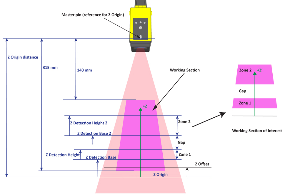
If Zone 1 and Zone 2 are enabled, the Working Section of Interest is defined as follows:
If Zone 1 and Zone 2 are not bridged (default) and a gap exists between the two zones (the zones are not touching each other), detection is performed in the zones and detection is not performed in the gap.
In the special case when the two zones are touching each other, generally, Zone 1 and Zone 2 are combined into a single zone starting at the bottom of the lowest zone and ending at the top of the highest zone. Detection is performed in this combined zone using the individual ZDetectionSampling setting for each zone. The one exception is the case when ZDetectionSampling is set to 2 and ZDetectionSampling2 is set to 1; in this case there will be a gap of 4 intensity image rows at the border of the two zones in which no detection will be performed. If you do not want this gap to be present, you can bridge the two zones.
- If Zone 1 and Zone 2 are bridged by enabling the BridgeDetectionZones parameter, Zone 1 and Zone 2 are combined into a single zone starting at the bottom of the lowest zone and ending at the top of the highest zone. The ZDetectionSampling setting from Zone 1 is used for the entire combined zone.
You use the ZScale range image parameter to specify in mm the scaling of pixel values; i.e. you specify the mm/pixel value resolution in the Z direction using this parameter.
By default, the pixel value of 1 represents the (Z Origin + 1 x ZScale) height. You may specify a custom height value (in mm) to correspond to the pixel value of 1 by using the ZOffset range image parameter, which is added to the Z Origin. This way, you transform the Z axis to a virtual Z axis by moving its origin.
Note: Heights at Z Origin (or ZOffset) are also represented by the pixel value of 1 (instead of 0). Also, the heights returned in mm by the 3D transform in the range image are always expressed relative to the Z Origin, even if a nonzero ZOffset has been specified. In other words, changing the ZOffset changes the pixel value representation, but not the fact that range image heights are always expressed in the Sensor3D Space.
The ZOffset height is the furthest point from the displacement sensor that is measured, detected heights below (further from) this are indicated with the pixel value of 1 in the 16-bit height profile image component of the range image. Heights below or above the Working Section (or Working Section of Interest) are undetected, and shown as missing pixels in the Visible Pixel Mask range image component (meaning “no data”). They appear with the value of 0 in the 16-bit height profile image component of the range image.The following figure shows how range image pixels depend on the above acquisition parameters. Nonzero valid pixel values in 16-bit height profile image component of the range image are only generated in the valid range; missing pixels are generated outside of the valid range.
When ZScale is positive, pixel values increase towards the camera. When ZScale is negative, pixel values increase away from the camera. In this latter case, the direction of the Z axis becomes inverted, as a result the range image will become inverted (that is, darker values will represent greater heights), and ZOffset becomes the nearest point from the displacement sensor that is measured.
The following figure shows three different cases when ZScale is negative:Quantization:
The following figure shows how quantization is performed in the case when ZScale is positive.
Note: Other concepts, such as the concept of missing pixels and upper and lower detection limits, are not shown here in detail.
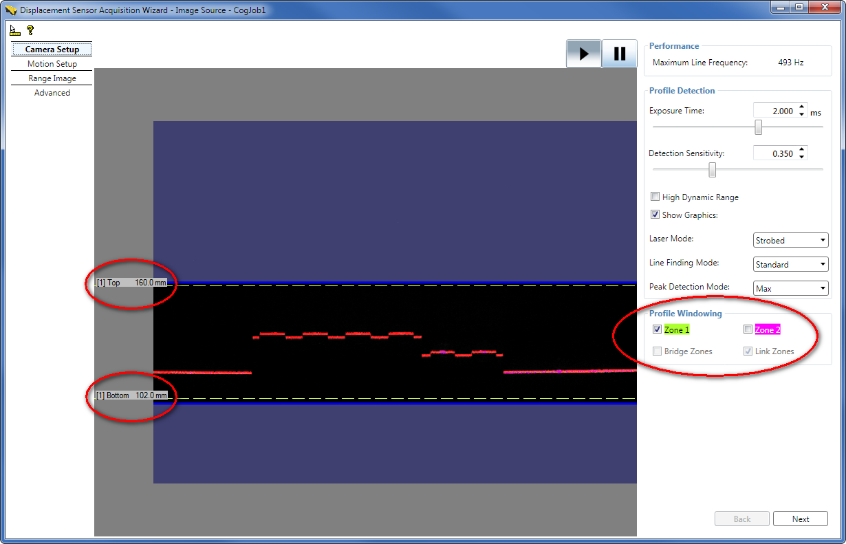
You can use the DetectionSensitivity parameter to set the sensitivity of the laser detection. A higher value makes the laser easier to find and allows a lower exposure setting, which in turn may allow a higher line frequency. A lower value will prevent mistaking noise for the laser in areas where the laser is obscured.
The following figure shows the Camera Setup tab in the Displacement Sensor Acquisition Wizard, with some of the parameters related to the Z axis:
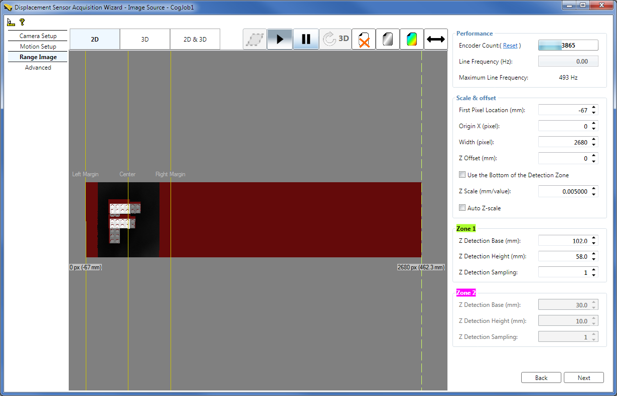
The following figure shows some of the acquisition properties for the X axis:
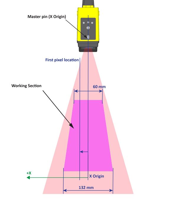
Once you have specified the left edge of the region to acquire (in mm from the master pin), in the pixel space, you can specify the following for your range image:
- The X origin offset of the range image using the Origin X field on the GUI.
- The width of the range image using the Width field on the GUI.
- In the API, use the ICogAcqFifo.OwnedROIParams.SetROIXYWidthHeight(int OriginX, 0, int Width, int HeightY) method of the DS900 and DS1000 ICogAcqFifo object to specify the above parameters for your range image.
You use the XScale range image parameter to specify the dimensions of range image pixels, in mm, in the X direction. It defaults to the scaling of sensor pixels at the closest distance from the camera that can be measured. The default setting ensures no information loss in range images. The DS1100 model has an integrated camera sensor with a resolution of 1024 x 768 pixels. The following figure illustrates the resolution change in the X direction, along the Z axis:
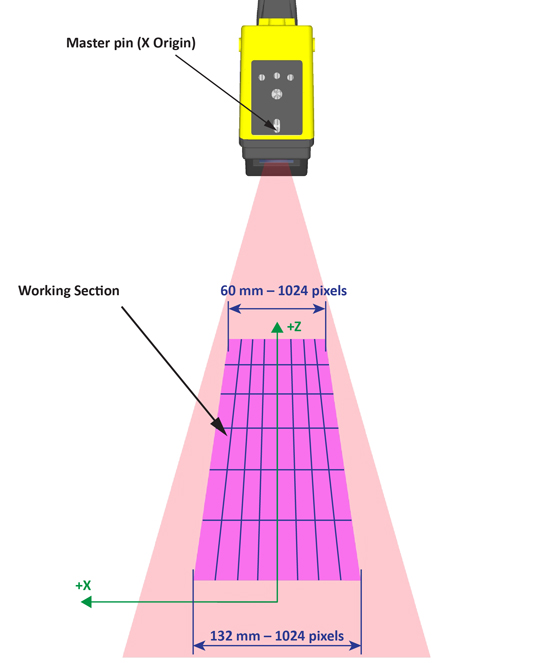
Note: If you wish to specify the width of the region to acquire in mm, you must use XScale to convert from mm to pixels.
The following figure shows a range image acquired from a Job with a DS1100 sensor in the push direction, using the following parameters: FirstPixelLocation = −67 mm; Width = 600 pixels; XScale = 0.2 mm/pixel; Origin X = 0 pixel; (YScale = 0.2 mm/pixel; Scan Length in Pixel = 700 pixels; Steps per Line = 10; DistancePerCycle = 0.08 mm/cycle; EncoderResolution = 4x – dual channel encoder)
The optimal representation of a certain height in a range image is achieved if neither undersampling (causing loss of information), nor oversampling (causing superfluous range image sizes in the X direction), is performed during the X scaling operation. A method to calculate the optimal X scaling at a certain height is to divide the width of the Working Section at that height by 1024 (the horizontal resolution of the integrated camera sensor of the DS1100 model). Therefore, if you know the greatest height that you will want to measure passing through the Working Section, and you do not want to lose information, you can achieve an optimal representation by calculating the X scaling of the sensor pixels at that greatest height and setting this as the XScale parameter. In this case, the representation will be optimal at the greatest height, and oversampling will occur at lesser heights.
Working with Wide Objects
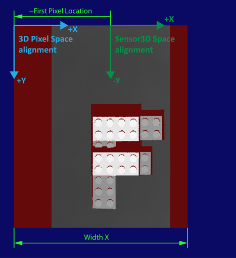
You can also acquire range images of objects with surfaces whose widths exceed the Working Section width. The following figure shows the range image acquisition of an object that is wider than the Working Section:
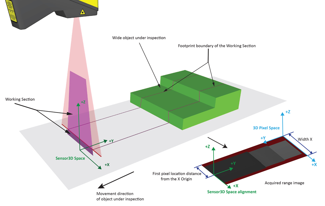
The origin of the Y axis is at the top edge of the first acquired range image row of pixels. Further acquired range image rows are added to the range image, each new row being associated with an incremented Y axis value. You specify encoder parameters (as outlined in the Acquiring Images from a DS900 Series Sensor and Acquiring Images from a DS1000 Series Sensor topics) that determine how much physical travel elapses between acquired rows of the range image. If the rows are acquired too frequently (that is, too close to each other), the range image will appear stretched. If not enough rows are acquired, the image will appear squashed. When the encoder characteristics are set up so that the line frequency matches the X-resolution, features in the range image will appear with the same aspect ratio as they appear in the real world.
The YScale corresponds to the number of millimeters per row in the acquired image.
To preserve the aspect ratio of the object under inspection in the range image (that is, range image pixels represent square areas in real world dimensions), the scale in the X direction must match the scale in the Y direction.
Note: For more information regarding preserving aspect ratio, see the Acquiring Images from a DS900 Series Sensor and Acquiring Images from a DS1000 Series Sensor topics.
The Scan Length in Pixel parameter defines the size of the range image along the Y axis, i.e. the number of range image lines acquired.
The following figure shows a range image acquired from the Job with a DS1100 sensor in the push direction, using the following parameters: Scan Length in Pixel = 700 pixels; YScale = 0.2 mm/pixel; (XScale = 0.2 mm/pixel; Steps per Line = 10; DistancePerCycle = 0.08 mm/cycle; EncoderResolution = 4x – dual channel encoder; FirstPixelLocation = −67 mm; Width = 600 pixels; Origin X = 0 pixel)
To express information in a different physical coordinate space than the default Sensor3D, you can add your custom 3D coordinate spaces to the range image's 3D coordinate space tree. The range image 3D coordinate space tree is analogous to the 2D coordinate space tree of a 2D VisionPro image, described in the Coordinate Space Trees topic. The difference is that this tree contains 3D coordinate spaces.
The range image 3D coordinate space tree contains the following spaces:- Root space ("@")
- Sensor3D space
- Any other custom 3D physical coordinate spaces you define
The size of the range image along the Y axis (Scan Length in Pixel) is limited as follows if HighDynamicRange is disabled:
Single Frame Mode (Manual and Hardware Semi-Auto trigger modes):
Max Scan Length in Pixel = 32,767 Number of Lines
This maximum height applies only if you do not queue starts, that is, if you wait until acquisition complete is returned before calling the start of the next acquisition or if you set the "Number of Software Acquisitions Pre-Queued" Job property to 1 in QuickBuild. The maximum image height for queued starts is 10,922. With queued starts, acquiring images of sizes greater than 10,922 and less than 32,767 may cause the DS1100 sensor to become unresponsive.Continuous Mode (Hardware Auto and Free Run trigger modes):
Max Scan Length in Pixel = 32,768 / 3 = 10,922 Number of Lines
If you request image sizes greater than this maximum height in the continuous mode, the DS1100 sensor will return images of this maximum height and will do so without throwing any errors.If HighDynamicRange is enabled, these values are halved.