Calculating the Volume of Features in 3D ImagesCognex VisionPro

This topic contains the following sections.

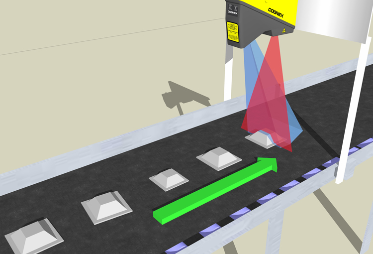
This topic describes volume calculation using range images acquired from a Cognex 3D displacement sensor. The 3D Range Image Volume Calculator tool calculates the volume of features in a range image in an area above a base plane which you define. The volume is returned in the units of the Sensor3D Space (cubic mm).

For example, you can use the 3D Range Image Volume Calculator tool to determine whether the volume of a part is in a specific volume range.

Image Processing Profile Plus Theory 3DVolume Calculator Illustration

For the theory of range images, acquired from displacement sensors, see the Working with 3D Range Images topic. For information on setting up acquisition with your displacement sensor, see the Getting Started topic. For detailed information on range image acquisition, see the Acquiring Images from a DS900 Series Sensor and Acquiring Images from a DS1000 Series Sensor topics. For advanced range image acquisition details, including coordinate spaces related to range images, see the Range Image Coordinate Spaces and Associated Parameters topic. For hardware-related information (such as mounting and physical product features) and further product details, see the DS900 Quick Reference Guide, DS1000 Quick Reference Guide, and the DS1000 Technical Reference Manual.

Volume Calculation

The 3D Range Image Volume Calculator tool takes the following inputs: the range image acquired about the object, a base plane above which volume calculation should be performed, and the 2D area in which volume calculation should be performed. You specify the 2D area using a Region and optionally an input image mask. In addition to these, the Visible Pixel Mask coming with the range image defines additional masking. You can also specify a Minimum Height Threshold relative to the base plane; pixels with heights below this are not included in the volume calculation.

The following figure shows a truncated pyramid (also known as frustum); the volume of a part of it will be measured:

Image Processing Profile Plus Theory 3DVolume Calculator volume calculation step 1
The truncated pyramid, from above, on the conveyor belt:
Image Processing Profile Plus Theory 3DVolume Calculator volume calculation step 1 top
The following figure shows the base plane applied, above which volume is calculated:
Image Processing Profile Plus Theory 3DVolume Calculator volume calculation step 2
The truncated pyramid from above, as the base plane is applied:
Image Processing Profile Plus Theory 3DVolume Calculator volume calculation step 2 top
The following figure shows the Region applied, within which volume is calculated:
Image Processing Profile Plus Theory 3DVolume Calculator volume calculation step 3
The truncated pyramid, from above, as the Region is applied:
Image Processing Profile Plus Theory 3DVolume Calculator volume calculation step 3 top
The following figure shows an input image mask applied, which masks out a portion from the volume calculation:
Image Processing Profile Plus Theory 3DVolume Calculator volume calculation step 4
The truncated pyramid, from above, as the input image mask is applied:
Image Processing Profile Plus Theory 3DVolume Calculator volume calculation step 4 top
The following figure shows the part of the truncated pyramid, whose volume will be measured:
Image Processing Profile Plus Theory 3DVolume Calculator volume calculation step 5
The truncated pyramid part, from above, whose volume will be measured (after the Region and the input image mask have been applied):
Image Processing Profile Plus Theory 3DVolume Calculator volume calculation step 5 top
The only major difference between the volume of this part of the truncated pyramid and the measured and returned volume, will be the volume of invisible areas, (the areas represented by missing pixels in the Visible Pixel Mask).

The following image shows the range image acquired of the truncated pyramid:
Image Processing Profile Plus Theory 3DVolume Calculator volume calculation step 1 top range image
In the following image, the area enclosed in purple shows the portion of the range image that is used for volume calculation based on the Region (whose border is marked with green), the input image mask (whose border is marked with red), and the base plane:
Image Processing Profile Plus Theory 3DVolume Calculator volume calculation step 1 top range image used
The missing pixels (marked with dark red) do not contribute to the calculated volume.

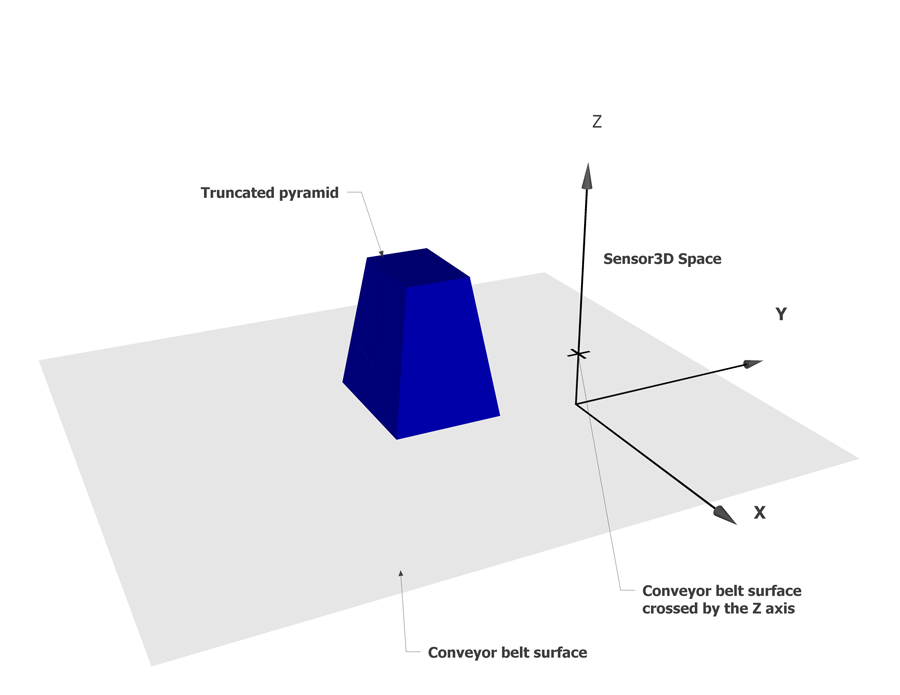
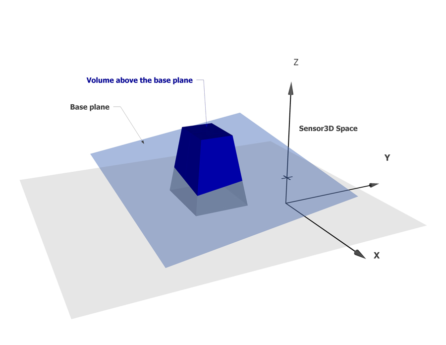
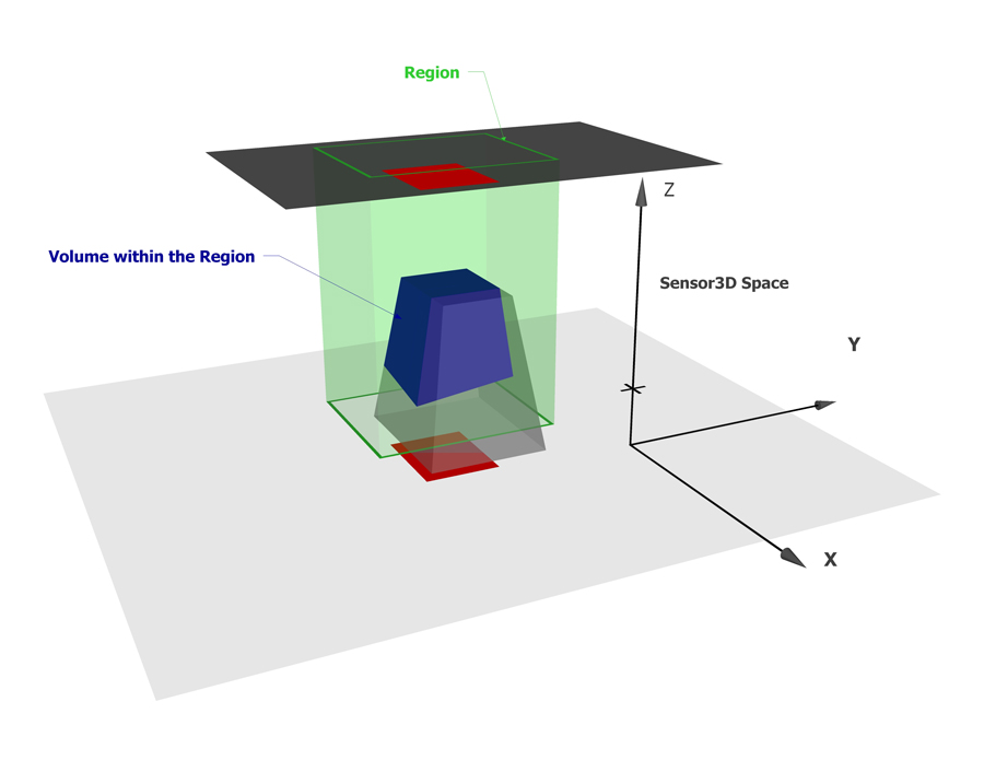
The volume calculator tool measures the volume enclosed between the surface of the range image data and one side of the base plane.

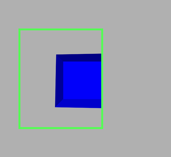
For a range image pixel to contribute to the computed volume, the range image pixel must meet the following requirements:
  • It must be within the 2D Region.
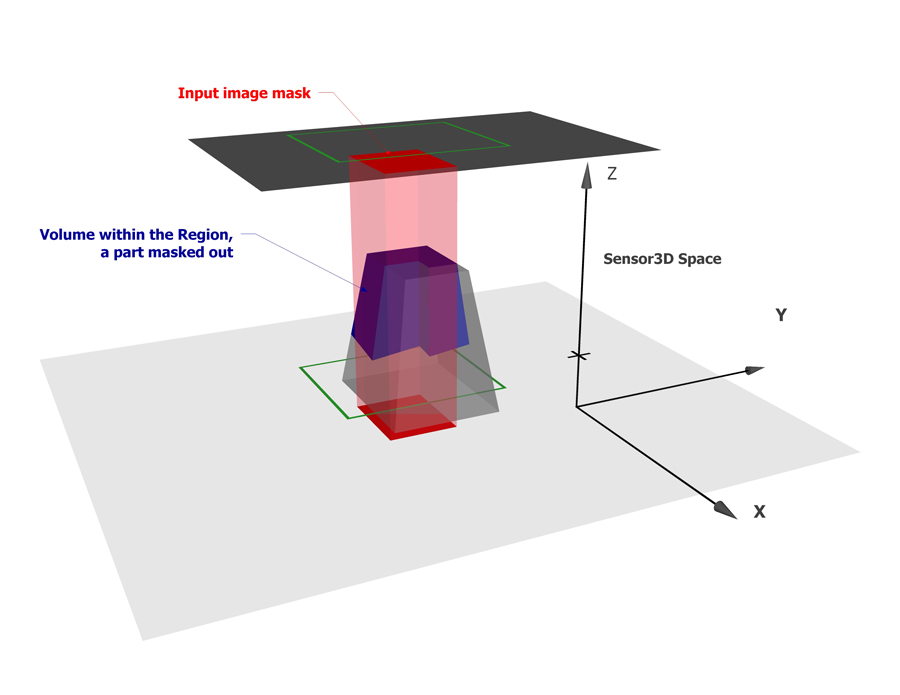
  • It must be marked as "Care" if an input image mask is provided.
  • It must be marked as visible in the range image's Visible Pixel Mask.
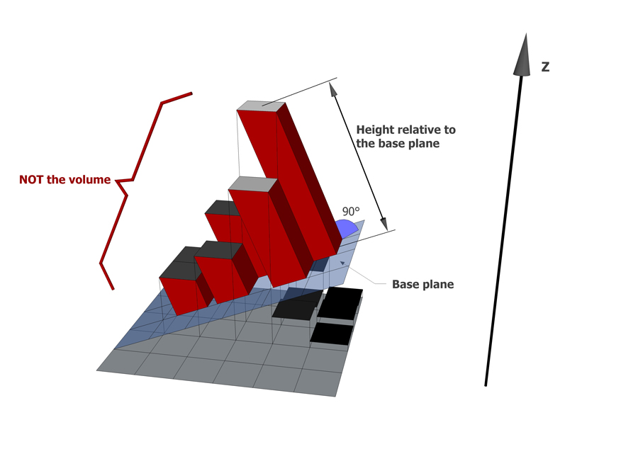
  • It must have a height relative to the base plane that is greater than or equal to the Minimum Height Threshold.
The volume represented by range image pixels is calculated as projections along the Z axis, as shown in the following figure:
Image Processing Profile Plus Theory 3DVolume Calculator volume calculation volume
The volume represented by range image pixels is not calculated as projections to the base plane. However, the height of a pixel is measured as the distance from the base plane, when validating it against the Minimum Height Threshold.
Image Processing Profile Plus Theory 3DVolume Calculator volume calculation novolume

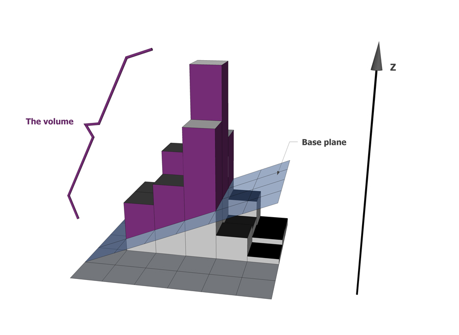
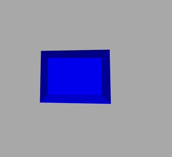
The tool marks those range image pixels that contribute to the computed volume with a purple color on the display.

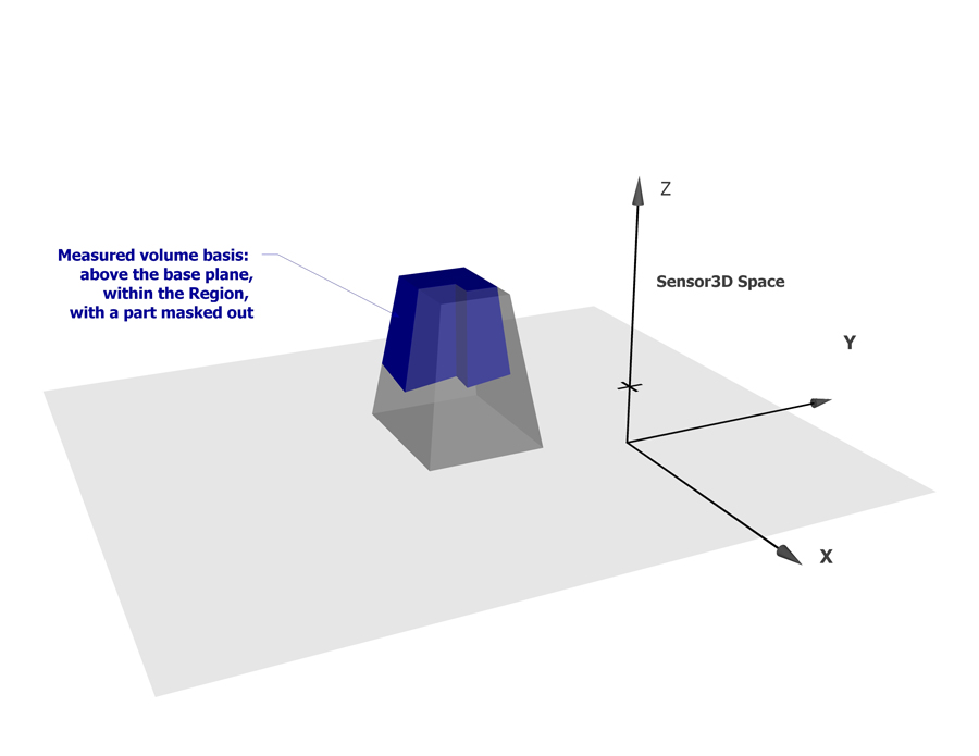
The following figure shows a frustum, with a rim, while its volume is being measured using a rectangular Region (whose border is marked with green) and a base plane that is the measured plane of the conveyor belt on which the frustum rests. (No input image mask is used.)
Image Processing Profile Plus Theory 3DVolume Calculator volume calculation frustum example 1
The measured volume is around 126000 cubic mm. Notice that the missing pixels are not used for volume calculation, therefore, they appear with the default dark red missing pixel color and not purple. Also notice that due to the uneven surface of the conveyor belt, some pixels about the conveyor belt are used for volume calculation while others are not. If you want to exclude the pixels near the base plane, increase the Minimum Height Threshold.

The following figure shows the same scenario, with the Minimum Height Threshold set to 10mm:
Image Processing Profile Plus Theory 3DVolume Calculator volume calculation frustum example 2
The measured volume is around 95000 cubic mm. Note that this volume is greater than the volume measured above the plane defined by the edge of used pixels (the edge of the purple mask), because the volume is measured above the base plane, which is situated lower.

You can specify on which side of the base plane the volume calculation should be performed (i.e whether the Normal with a positive Z coordinate value, or the Normal with a negative Z coordinate value, should be used). For more information on plane sides, see the section about specifying which side of the plane is above the plane.

In addition to the calculated volume, the tool also returns diagnostics data about how the range image pixels were used to calculate the volume: the number of pixels in the Region; the number of Care (unmasked) pixels; the number of visible Care pixels; and the final number of pixels that were used during volume calculation based on the Region, the masks, and the Minimum Height Threshold.

Region Types

You can choose volume calculation to be performed within the following Region types:

  • Circle
  • Ellipse
  • Circular or elliptical annulus section
  • Rectangle or affine rectangle
  • Custom polygon
  • The entire image