The 3D Range Image Plane Estimator fits a geometric Cog3DPlane based on select information taken from a 3D range image. The tool returns a set of properties about the plane including its tilt, a normal (perpendicular) vector to the plane, and the offset between the plane and the origin of your 3D coordinate space along the normal vector.
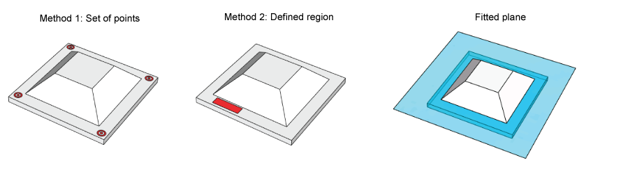
A 3D Range Image Plane Estimator generates a plane either from analyzing specific points or a defined region of a 3D range image:
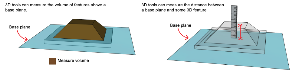
Plane estimation is an initial step in 3D vision applications involving volume measurement or height calculation:
See the following sections for more information:
As you configure a 3D Range Image Plane Estimator you must choose whether it fits a plane to discrete points or an enclosed region of a 3D range image.
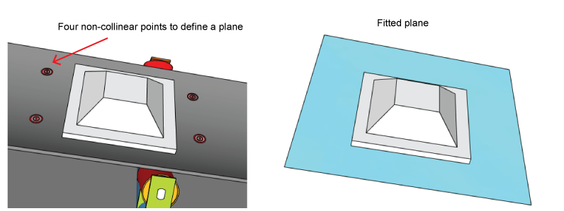
You can choose plane fitting based on the Z-value (height) of a set of non-collinear points. By default the tool uses four points, and will not execute with fewer than three points. In the following figure the points define a plane parallel to the moving conveyor belt:
The height value to use for each point can be derived from one of the following methods:
Single Pixel
The height value is taken from the pixel with the corresponding (X,Y) coordinate in the 3D range image.
Neighborhood Median
A single value is calculated from the median of an NxM neighborhood around each point with the corresponding (X,Y) coordinate in the 3D range image.
Neighborhood
The height value for all the pixels within an NxM neighborhood are used for plane fitting.
The running time of a 3D Range Image Plane Estimator increases with the number of points used during plane fitting.
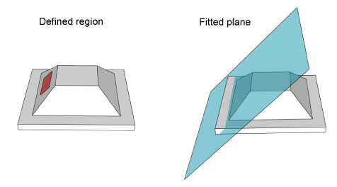
You can choose plane fitting based on a region of the 3D range image you specify. Although you can allow to the tool to consider the entire 3D range image, most applications use a defined shape for the input region. The Z-values (height) of the pixels within the region define the resulting fitted plane:
As you configure a 3D Range Image Plane Estimator you can choose between two types of algorithms for generating the fitted plane:
- Fit a plane to all of the specified 3D points, whether they were specified via discrete points or by a region.
Fit a plane to a subset of the specified 3D points, as determined by the Adaptive RANAC algorithm.
Cognex uses a custom version of the RANSAC algorithm, an iterative method to estimate which input 3D points generate the most accurate fitted plane. See the topic The RANSAC Algorithm for more information on the algorithm, which is used by several Cognex vision tools.
A 3D Range Image Plane Estimator generates a number of results to describe the fitted plane.
The normal to the fitted plane is a vector perpendicular to the plane from a given origin:
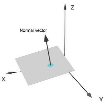
A 3D Range Image Plane Estimator defines the normal with a unit vector whose origin is the origin of the 3D coordinate system.
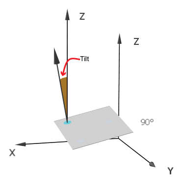
The tilt of the plane is defined as the angle between the plane Normal and the Z-axis. It is normalized to the range [0, pi]:
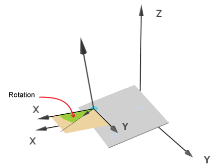
The rotation of the plane is defined as the angle between the perpendicular projection of the plane Normal on the XY-plane and the X-axis. It is normalized to the range [0, pi * 2):
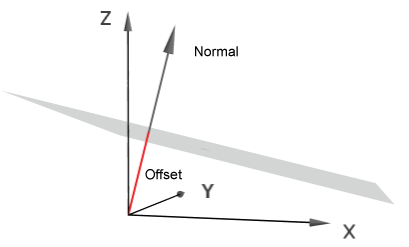
The offset of the plane is the distance of the plane from the origin (along the plane's normal). The following image shows the found plane and its offset from the origin (in red):
As you configure the tool you specify whether the normal to the fitted plane is generally positive ("pointing up") or negative ("pointing down") when compared to the image coordinate system Z-axis. Be aware the tool can produce two mathematically distinct planes from the same set of input points depending on the normal direction that you specify.
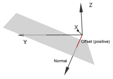
The following figure depicts a case when the fitted plane crosses the Z axis below the Z Origin and the plane's normal is in the "pointing down" direction. The offset of the resulting plane (in red) is a positive value, because it travels from the origin to the plane in the same direction as the plane normal:
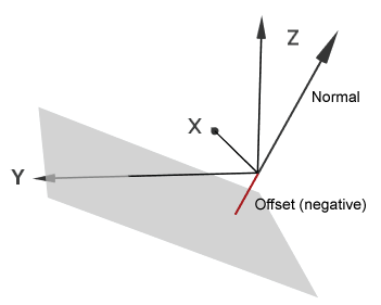
The following figure depicts a plane fitted to the same input data, but with the normal in the opposite direction. In this case, the resulting offset (in red) is a negative value, because it travels from the origin to the plane in a direction that is exactly opposite to that of the plane normal:
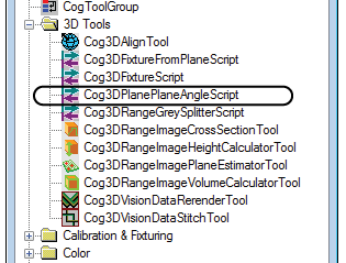
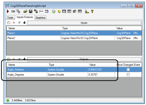
QuickBuild offers a preconfigured CogToolBlock that you can use to find the angle between two fitted planes. Add a Cog3DPlanePlaneAngleScript from the 3D tools list of vision tools in the ToolBlox:
The Cog3DPlanePlaneAngleScript CogToolBlock accepts two fitted planes and uses predefined script to determine the angular difference between the normal vectors of each plane. The CogToolBlock makes the angular difference available in radians and degrees:
VisionPro includes a sample QuickBuild application that uses a Cog3DPlanePlaneAngleScript CogToolBlock.
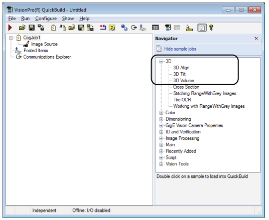
VisionPro includes a set of sample QuickBuild jobs that all use a 3D Range Image Plane Estimator:
3D Align
Demonstratres 3D alignment and the rerendering of 3D range images
3D Tilt
Demonstrates the calculation of tilt between fitted planes
3D Volume
Demonstrates 3D volume calculation
Access the sample QuickBuild jobs through the QuickBuild Navigator: