This topic contains the following sections.
In VisionPro, the PMAlign tool uses Cognex PatMax software to perform pattern location.
| Term | Definition |
| alignment | The process of running PatMax to search a run-time image for matches on a trained pattern |
| boundary point | A point along a feature boundary. A boundary point has a location and an orientation (normal to the feature boundary and in the direction of positive intensity change) |
| clutter | Extraneous features in a run-time image that are not part of the trained model |
| deformation | A change in a pattern that cannot be described using a linear transformation |
| deformation rate | A measure of the degree to which a found pattern is deformed from a trained pattern |
| degree of freedom | Part of a transformation that can be characterized by a single numeric value such as angle |
| feature | A continuous boundary between regions of dissimilar pixel values. A feature is represented by a list of boundary points |
| generalized degree of freedom | A degree of freedom other than x-translation or y-translation. For example: uniform scale, x-scale, y-scale, or rotation. |
| granularity | A measure of the minimum detected feature size in an image. |
| pattern | A trained (internal) geometric description of an object you wish to find in run-time images |
| run-time image | Image in which to locate instances of the trained pattern |
| score | Numerical measure of the similarity between the pattern in the trained model and the pattern in the run-time image |
| shape model | A shape model object is composed of a geometric shape, such as a line segment, circle, polygon, or general contour, a polarity (whether a line drawn normal to the shape goes from dark to light or light to dark), and a weight (how heavily to weight this shape when scoring a pattern instance. |
| shape training | The process of training a PatMax pattern using one or more shape model objects. |
| transformation | Mathematical representation of the equations that describe the conversion of points from one coordinate system to another coordinate system. |
This section contains the following subsections.
Like other pattern-location technologies, PatMax trains a pattern, then locates one or more instances of that pattern in one or more run-time images. PatMax differs from other pattern-location technologies in that it is not based on pixel grid representations that cannot be efficiently and accurately rotated or scaled. Instead, PatMax uses a feature-based representation that can be transformed quickly and accurately for pattern matching.
PatMax can be trained from an image that contains features similar to those you wish to find at run time, or it can be trained from a geometric description of the target features. PatMax training results in a pattern that contains geometric features.
Figure 1. PatMax training
The PatMax software supports two pattern-location algorithms: PatMax and PatQuick. PatMax offers higher accuracy and additional score information compared to PatQuick, but requires more time to execute.
PatMax extracts patterns from the images of objects you acquire. A PatMax pattern is a collection of geometric features and the spatial relationship between them, where each feature is a collection of points on the boundary between two regions of dissimilar pixel values.
Figure 2 shows an image, the corresponding PatMax pattern it generates, and the features that make up the pattern.
Figure 2.
The appearance of an object in an image can vary in several different ways. PatMax can find objects whose appearance varies in any or all of the following ways:
- Size (overall size change or individual x- and y-axis size change)
- Rotation
- Location
Each of these types of transformation is called a degree of freedom, and is illustrated in Table 1:
| Degree of Freedom | Examples |
| X translation |  |
| Y translation |  |
| Rotation |  |
| Uniform scale |  |
| X scale |  |
| Y scale |  |
In many applications, the appearance of an object can undergo several types of transformations at the same time. Figure 3 shows examples where a pattern experiences transformations in multiple degrees of freedom:
Figure 3. Combining degrees of freedom
PatMax finds trained patterns in run-time images no matter what combination of transformations the pattern has undergone. You can limit PatMax to consider particular degrees of freedom, and within a degree of freedom, only a specified range. By doing this you can ensure that PatMax finds all of the variations that your application encounters in the smallest amount of time.
For each instance of the pattern that PatMax finds in a run-time image, PatMax returns the location of the instance as well as values for each of the degrees of freedom of the transformation the pattern has undergone.
PatMax also computes a score between 0.0 and 1.0 that provides an indication of how closely the pattern in the run-time image matches the trained pattern after accounting for the transformation that the pattern has undergone.
This section contains the following subsections.
- PatMax Patterns
- How PatMax Finds Patterns in an Image
- Controlling PatMax Alignment
- Degrees of Freedom
- Expected Result Count and Accept Thresholds
- Non-Linear Pattern Deformation
- Ignoring Clutter When Scoring
- Run-Time Image Masking
- Controlling Overlap Tolerance
- Degenerate Results
- Working with Non-square Pixels
- AutoTune using Composite Pattern Training
The information in this section will help you understand how to get the most out of PatMax.
This section contains the following subsections.
When you train PatMax you specify a region of interest in an image or provide a description of a shape that includes the features you want to train. If you are using an image to train the PatMax software, PatMax constructs an internal geometric representation of the features that make the pattern, where features are defined by boundaries between regions of dissimilar grey values. If you are using a shape description to train the PatMax software, PatMax transforms the model information into this same internal geometric description. Once trained, PatMax execution is the same regardless of whether PatMax was trained with an image or with a shape description.
Pattern Features
A PatMax pattern is a collection of features. An individual feature is defined to be a continuous boundary between regions of dissimilar pixels. The regions can have different intensity, contrast, or texture, and can be open or closed.
Figure 4 shows examples of open and closed features in an image.
Figure 4. Open and closed features
PatMax pattern features are represented by an ordered list of feature boundary points. A feature boundary point has a location and an angle along with links to its neighboring boundary points. The angle of a feature boundary point is the angle between the image coordinate system x-axis and a line drawn through the feature boundary point perpendicular to the feature boundary and in the dark-to-light direction.
Figure 5 shows the feature boundary points that define a pair of features.
Figure 5. Feature boundary points
Feature Size and Pattern Granularity
The features that make up a pattern can be of different sizes, from features a few pixels in size to features up to 50 or 100 pixels in size. Most patterns contain features with a range of sizes.
PatMax uses features of different sizes to locate the desired features in the run-time images you acquire. In general, PatMax uses large features to find an approximate pattern match in a run-time image quickly, and small features to determine the pattern location precisely.
Figure 6. Large features used for coarse location and small features for fine location
The particular features that PatMax can detect in an image are determined by the granularity the PatMax software is currently using. Large granularity settings allow the software to detect only large features in an image, while a smaller granularity setting allows the tool to locate smaller features.
Granularity is expressed as the radius of interest, in pixels, within which features are detected. Figure 6 illustrates two important characteristics of pattern granularity.
- Large features are detected at both small and large granularity settings.
- Smaller features are present or absent from the image depending on the granularity setting.
In some cases, however, a feature might be present at a fine granularity and at a coarse granularity, but not at an intermediate granularity.
Figure 7 shows the effect of different granularity settings on the features that are detected in a single image.
Figure 7. Pattern granularity
In addition to affecting the features that are trained as part of the pattern, pattern granularity also affects the spacing of boundary points along a feature boundary. In general, the spacing of feature boundary points is approximately equal to the pattern granularity.
PatMax uses a range of pattern granularities when it trains a pattern from an image; PatMax automatically determines the optimum granularity settings when it trains a pattern. The smallest granularity used to detect features in the training image or shape description is called the fine granularity limit. The largest granularity used to detect features is called the coarse granularity limit.
You can display the actual features and feature boundary points trained using the coarse and fine granularity limits.
Note: PatMax trains the pattern using a range of granularities, not just the coarse and fine granularity limits. The coarse and fine limits are the largest and smallest granularities that PatMax uses.
Pattern Polarity
Each of the boundary points that describes a pattern feature has a polarity. The polarity of a boundary point indicates whether the boundary can be characterized as light-to-dark or dark-to-light. You can configure PatMax to find only objects in which every boundary point has the same polarity as the trained pattern, or you can configure PatMax to find objects with mismatched polarity.
Ignoring pattern polarity increases the variety of patterns that PatMax finds. Figure 8 shows some examples of matched and mismatched pattern polarities. If you configure PatMax to ignore pattern polarity, it finds all of the patterns shown in Figure 8. If you configure PatMax to consider pattern polarity, it might not find the patterns in the right-hand column, or it might find them but assign them lower scores than the patterns in the left-hand column.
Figure 8. Pattern polarity
If the run-time images encountered by your application can undergo polarity or other non-uniform changes in brightness, and you want to locate objects that have experienced these kinds of brightness changes, you should configure PatMax to ignore pattern polarity. If you want PatMax to find only patterns with matching polarity, you should configure PatMax to consider pattern polarity.
If you are using shape training, the polarity of all of the shapes being trained must be defined in order to consider pattern polarity; if any shapes have indeterminate polarity, you must ignore pattern polarity
Note: Ignoring pattern polarity causes PatMax pattern location to be approximately 10% slower than considering pattern polarity.
Pattern Masking
When you train PatMax using an image, you can exclude features from the trained pattern by supplying a mask image.
Figure 9 shows an example of how you would use a mask to exclude some features from being used in the trained pattern.
Figure 9. Masking image
Using a mask lets you exclude features which might vary between different objects while still finding the pattern using a full range of granularities.
Note: Pattern masking is not supported for shape training since you can design your shape description to include only desired features and thus have no need to mask out unwanted features.
The mask image is interpreted as follows:
- All pixels in the training image that correspond to pixels in the mask image with values greater than or equal to 192 are considered care pixels. All feature boundary points detected within care pixels are included in the trained pattern.
- All pixels in the training image that correspond to pixels in the mask image with values from 0 through 63 are considered don't care but score pixels. Feature boundary points detected within don't care but score pixels are not included in the trained pattern. When the trained pattern is located in a run-time image, features within the don't care but score part of the trained pattern are treated as clutter features.
- All pixels in the training image that correspond to pixels in the mask image with values from 64 through 127 are considered don't care and don't score pixels. Feature boundary points detected within don't care and don't score pixels are not included in the trained pattern. When the trained pattern is located in a run-time image, features within the don't care and don't score part of the trained pattern are ignored and not treated as clutter features.
- Mask pixel values from 128 through 191 are reserved for future use by Cognex.
Note: If you use the PatQuick algorithm (which does not consider clutter pixels), then mask image pixel values from 0 through 63 are treated the same as mask image pixel values from 64 through 127.
This section contains the following subsections.
- Run-time Space
- Pattern Granularity
- Run Mode
- High Sensitivity Mode
- Sensitivity Parameter
- Pattern Weights
- Pattern Transformations
- Generalized Pattern Origin
- Score
- Contrast
- Fit Error, Coverage, and Clutter
This section describes how PatMax finds and reports pattern matches in run-time images.
Run-time Space
When you search for a PatMax pattern in a run-time image, you define the run-time space that PatMax uses. The run-time space is determined by the degrees of freedom you enable, and the range of values to consider within each degree of freedom.
PatMax identifies likely candidates within the run-time space, then determines the transformation that best describes the transformation from the trained pattern geometry to the transformed pattern geometry in the run-time image.
Pattern Granularity
PatMax locates pattern matches in the run-time space by first searching only for the large features. After locating one or more pattern matches, it uses smaller features to determine the precise transformation between the trained pattern and the pattern match in the run-time image.
By default, PatMax uses the same range of granularities that it computed when it trained the pattern to detect features in the run-time image.
Run Mode
PatMax supports two run modes for locating the pattern in each acquired image. By default, PatMax uses Search Image mode and searches the entire image for the pattern it is trained to find. PatMax also supports Refine Start Pose mode, which limits the search for the pattern to within a few pixels of a defined starting position, typically supplied by another vision tool. Using Refine Start Pose mode, PatMax does not use its coarse granularity settings to search the image for larger features, and instead moves to a refined search for the smaller features assuming they are located within an extremely narrow range of the given starting position.
High Sensitivity Mode
Image quality can have a significant affect on PatMax's success in finding features in images. Clear, sharp, high contrast images generally yield the best results while low contrast and noisy images can be problematic. To better enable PatMax to handle this range of image quality, two execution modes are provided. For good images with low noise and high contrast, you should run the tool in standard mode, the normal mode of operation. If your images are noisy or have low contrast you may improve your results by running the tool in high sensitivity mode which will generally require more training time and more execution time. Figure 10 shows examples of good and problematic images. Note that high sensitivity mode performance may be worse than standard mode for patterns with small features. Cognex recommends standard mode for most applications.
Figure 10. Image examples
Sensitivity Parameter
When you use high sensitivity mode you can also set the sensitivity training parameter which allows you to specify your image quality. The sensitivity parameter is a number in the range 1.0 through 10.0 that specifies the amount of noise rejection PatMax applies to run-time images. If the sensitivity parameter is set to 1.0, minimum noise rejection is applied. If the sensitivity parameter is set to 10.0 PatMax applies the maximum noise rejection. Since portions of the pattern may appear as random noise, actual pattern features may be lost. Best results are usually achieved by using the default of 2.0. Lower sensitivity parameter values have less of an affect on training time and execution time whereas higher values tend to increase these times.
If you are having problems when using the default value of 2.0, and you suspect the cause is low contrast or noisy images, you can experiment by changing the sensitivity parameter to determine an optimum setting. Increase the sensitivity parameter to make PatMax less sensitive to random noise, and decrease the sensitivity parameter to make PatMax more sensitive to the pattern. If this helps you should find your optimal setting in the range 1.0 through 5.0. It is very unlikely that a setting above 5.0 will produce an optimal result.
Pattern Weights
When you use PatMax shape training, you supply a collection of individual shape models. Each of these shape models can be assigned a weighting factor that is used when running the tool to compute a score for how well the trained model matches the likeness found, as described in the section Assigning Weights. Shape models with larger weighting factors have more effect on the score.
Pattern Transformations
This section contains the following subsections.
When you train a pattern with PatMax using either shape description or an image, PatMax creates an internal representation of the pattern's geometry. PatMax also initializes the pattern origin to a value that you specify. When PatMax returns the location of a pattern instance in a run-time image, it does so in terms of the pattern origin.
Note: In addition to specifying the pattern origin as a simple point, you can also specify a generalized pattern origin in the form of a transformation object. The use of a generalized pattern origin is described in the section Generalized Pattern Origin.
By default, the pattern origin is located at (0, 0) within the selected space of the training image. Figure 11 shows the default pattern origin for a trained pattern.
Figure 11. Pattern origin
Pattern Transformations and Shape Training
When you train PatMax using image training, it uses the selected space of the training image to relate the features in the image and the pattern origin you specify, to the root space of the training image.
For shape training, you must provide information that relates the shape models you supply to the root space of a hypothetical training image. You can provide this information in either of two ways.
- You can provide a training image with an associated coordinate space tree that defines the selected space of each of the shape models you are training.
- You can provide a CogTransform2D object that provides a pixel from shape model transformation.
PatMax requires the information provided using these methods so that it can compute the appropriate granularity limits for pattern training.
Note: Keep in mind that the features in the trained pattern are not the same as the shapes you provide for training. If, for example, you provided a shape that was extremely small (less than 1 pixel in size), there would be no point in training that shape as a feature, since it would not be resolved in any run-time image.
Pattern Transformation Result
When you run PatMax, it returns a transformation that describes how the trained pattern maps into the found instance. You can use the information in this transformation in two ways:
- As a transformation object that you can use to convert any location from the trained pattern to the corresponding location in the run-time image. You can use the transformation object to transform points between the selected space of the trained pattern (translated by any nonzero pattern origin) and the selected space of the run-time image.
- As individual values for the ordinary degrees of freedom (the location of the pattern origin) and individual values for each of the generalized degrees of freedom that you have enabled
Figure 12 shows an example of a pattern being translated, scaled in the y-axis, and rotated. While you could use the individual values for translation, y-scale, and rotation change to compute where the point of interest is in the run-time image, simply applying the returned transformation object to the point of interest returns the new point of interest directly.
Figure 12. Using the transformation to locate points of interest
Generalized Pattern Origin
As described in the preceding section, PatMax returns a transformation object that describes how the pattern in the run-time image is different from the trained pattern. The returned transformation object describes the transformation between the trained pattern and the pattern in the run-time image, as shown in Figure 13.
Figure 13. Returned transformation (simple origin)
In some cases, you may want to apply a transformation to the trained pattern before you search for the pattern in a run-time image. You apply such a transformation by supplying a generalized pattern origin. PatMax applies the transformation you supply to the trained pattern before it searches for the pattern in the run-time image. When it returns a pattern location result, it returns the transformation between the trained, transformed, pattern and the pattern in the run-time image.
Figure 14 shows how you use a generalized pattern origin to scale a trained pattern before locating it in the run-time image.
Figure 14. Applying a generalized pattern origin transformation

You typically supply a generalized pattern origin to compensate for known scale or rotation changes in the trained pattern. If you supply a generalized pattern origin you should keep the following points in mind:
- PatMax will return results that describe the difference between the trained pattern after it has been transformed by the generalized pattern origin and the pattern in the run-time image.
- Any zone ranges and nominal values that you specify are interpreted with respect to the transformed trained pattern.
- Supplying a generalized pattern origin has no effect on the speed, accuracy, or number of results produced by PatMax.
- The x- and y-translation components of a generalized pattern origin are equivalent to the simple (point) origin.
Score
For each instance of the trained pattern that PatMax finds in the run-time image, it computes a score value between 0.0 and 1.0. The score an instance receives indicates how closely it matches the trained pattern. A score of 1.0 indicates a perfect match; a score of 0.0 indicates that the pattern does not match at all.
When you specify the PatMax algorithm, PatMax scores instances on both the closeness of pattern fit (the degree to which the shape of the features in the run-time image conforms to the shape of the features in the trained pattern) and the presence of clutter (extraneous features). When you specify the PatQuick algorithm, PatMax scores instances on pattern fit only.
In considering the fit, PatMax considers the shape of the pattern. Differences in brightness or contrast (as long as the polarity is the same) are ignored. (You can specify that PatMax ignore polarity changes in addition to brightness and contrast changes.)
PatMax is somewhat tolerant of elastic stretching of the pattern. PatMax tends to return lower scores for patterns with missing or extraneous features. Figure 15 shows examples of patterns with elastic stretching and patterns with missing or extraneous features (called broken patterns).
Figure 15. Pattern variations
In all cases, missing features lower the score an object receives. Extraneous features lower an object's score if you specify the PatMax algorithm and if you specify that PatMax consider clutter when computing scores. For more information on scoring and clutter, see the section Ignoring Clutter When Scoring.
Contrast
In addition to the overall score, PatMax also returns the image contrast of each instance of the pattern it finds in a run-time image. The contrast is the average difference in grey-level values for all of the boundary points that PatMax matched between the trained pattern and the pattern instance in the run-time image.
Since PatMax computes the score for a pattern based on the shape of the pattern, the contrast value and score value are generally independent. You can use the contrast value to get additional information about the object.
You can specify a contrast threshold for PatMax searches. If you specify a contrast threshold, only pattern instances where the average difference in grey-level values for all of the boundary points exceeds the contrast threshold are considered by PatMax.
Fit Error, Coverage, and Clutter
This section contains the following subsections.
When you specify the PatMax algorithm, PatMax returns three additional score values for each pattern instance it finds in the run-time image: the fit error, coverage score, and clutter score.
Note: These scores are only available if you specify the PatMax algorithm.
Fit Error
The fit error is a measure of the variance between the shape of the trained pattern and the shape of the pattern instance found in the run-time image.
The fit error is computed by taking the square root of the sum of the weighted average distances between each boundary point in the pattern and the corresponding boundary point in the pattern instance in the run-time image. If the pattern instance in the run-time image is a perfect fit for the trained pattern, the fit error is 0.0.
You can use the fit error to assess the degree to which the shape of a pattern instance matches the shape of the trained pattern.
Coverage Score
The coverage score is a measure of the extent to which all parts of the trained pattern are also present in the run-time image.
The coverage score is computed by determining the proportion of the trained pattern that is found in the run-time image. If all of the trained pattern is also present in the run-time image, the coverage score is 1.0. Lower coverage scores indicate that less of the pattern is present.
You can use the coverage score to detect missing or occluded features.
Clutter Score
The clutter score is a measure of the extent to which the found object contains features that are not present in the trained pattern.
The clutter score is the proportion of extraneous features present in the found object relative to the number of features in the trained pattern. A clutter score of 0.0 indicates that the found instance contains no extraneous features. A clutter score of 1.0 indicates that for every feature in the trained pattern there is an additional extraneous feature in the found pattern instance. The clutter score can exceed 1.0.
When PatMax computes the clutter score, it considers all features within the area in the run-time image that corresponds to the image area used to train the pattern, as shown in Figure 16.
Figure 16. Area considered when computing clutter
In the case of shape training, the area in which clutter affects score is defined by the training region.
Note: A common reason for using shape training is the presence of many variable and extraneous features in the images used by your application. When you locate shape-trained patterns in these images, there will likely be a large amount of clutter. In many cases, you should disable scoring clutter
This section describes how you control PatMax alignment, the process of finding likenesses of a trained pattern in run-time images.
This section contains the following subsections.
When you perform a pattern alignment using PatMax, for each generalized degree of freedom (a degree of freedom other than x-translation or y-translation), you must specify either
- That the degree of freedom is disabled, in which case you must specify a nominal value for that degree of freedom. PatMax will only find instances of the pattern that are close to the specified nominal value for that degree of freedom, and PatMax will not compute a value for that degree of freedom; it will report the nominal value that you specify for the degree of freedom. or
- That the degree of freedom is enabled, in which case you must specify a zone that defines the permitted range of values for that degree of freedom. PatMax will find instances of the pattern that have values for the degree of freedom within the specified zone, and PatMax will compute and report a value for the degree of freedom.
If, for example, you are using PatMax to perform translation-only alignment of fiducial marks, you might disable the rotation and scale degrees of freedom and specify nominal values of 0 degrees for rotation and 1.0 for scale.
However, if your application encounters run-time images where the fiducial marks are rotated or scaled very slightly, PatMax will find these instances, but the accuracy of the location information may be slightly reduced and the instance may receive a lower score. PatMax will not compute a value for scale or rotation; it will report the nominal value that you specify for the degree of freedom.
Figure 17 shows the effect of slight rotation when a nominal rotation value is specified and when a zone for rotation is specified. If a nominal value of 0˚ is specified for angle, a slightly rotated instance of the pattern is interpreted as a slight mismatch for the pattern. It receives a lower score (0.80 instead of 0.98), a higher fit error, and the accuracy of the position can be reduced.
Figure 17. Effect of setting nominal angle with small angle values
With each additional degree of freedom that you enable, PatMax requires additional processing time to analyze an image. In addition, the larger a zone you specify within a degree of freedom, the more processing time is required. For more information on optimizing alignment speed, see the section Optimizing PatMax Performance.
Finally, PatMax might return some model instances that are slightly outside the zone you specify. For example, if you specify a scale between 0.95 and 1.05, PatMax might return results with scale values of 1.09 or 0.91. You can always check the result values and exclude results that are outside the specified zone.
Specifying a nominal value for a degree of freedom lets you find patterns with small variations in the degree of freedom at the highest possible speed, since the degree of freedom is not part of the computation.
Image Confusion
As you increase the number of degrees of freedom and as you enlarge the zone for an individual degree of freedom, you increase the number of potential matches in a run-time image.
Figure 18 shows one effect of enabling a degree of freedom on the confusion of the image. With the scale degree of freedom disabled, only a single instance is found. With scale enabled, the top of the pattern is a fair match for a scaled instance of the entire pattern.
Figure 18. Image confusion increased with larger run-time space
In general, the larger the run-time space, both in terms of the size of the zone and in terms of the number of enabled degrees of freedom, the greater the potential for image confusion.
Effect of Non-Uniform Scale Degrees of Freedom
Enabling the non-uniform scale degrees of freedom in PatMax reduces the accuracy level to that of the PatQuick algorithm.
The x- and y-scale degrees of freedom allow you to specify variations from training to run-time objects that are called non-uniform scale variations, and provide alternative ways of specifying variations in aspect ratio from trained patterns to runtime objects. As with all generalized degrees of freedom, non-uniform scale variation can be specified using either nominal or zone parameters. Whenever a non-uniform scale zone is enabled, PatMax accuracy is limited to the lower accuracy of the PatQuick algorithm. Using non-uniform scale nominal values other than the default 1.0 results in no loss of accuracy.
If the aspect ratio of your objects truly varies, you may have no choice but to use a non-uniform scale zone and accept the lower accuracy. In some applications, however, aspect ratio does not vary from object to object, but is nevertheless different from the trained pattern. Do not use non-uniform scale zones to get PatMax to find the correct aspect ratio, because accuracy will be limited to the lower accuracy of the PatQuick algorithm. Instead use non-uniform scale nominal values, a calibrated coordinate space, or pattern coordinates to specify the fixed variation in aspect ratio from training to run-time.
When you search for a pattern using PatMax, you specify the number of instances you expect to be present in the run-time image and an accept threshold that specifies the minimum score value that an actual instance of the pattern is expected to receive.
PatMax returns information about all of the objects in the run-time image that receive scores above the accept threshold you specify up to the number of instances that you specify.
If there are multiple instances with similar scores, PatMax can return information about more instances than you specify. For example, if you specify an accept threshold of 0.50 and an expected result count of 2, and PatMax finds five instances with the following scores:
0.98
0.70
0.68
0.32
0.19
PatMax will return information about the first three instances, even though you only requested two. PatMax does this because of the potential ambiguity between the two results with scores of 0.70 and 0.68.
Cognex can make the following recommendations for setting the accept threshold:
- Specifying a low accept threshold forces the PMAlign tool to consider more potential matches while increasing the time required for the tool to execute. Specifying a high accept threshold allows the tool to eliminate non-matches and decreases the execution time, but at the risk of failure to locate an actual instance of the pattern.
- The tool uses a coarse accept threshold of 0.66 to help refine the alignment process when considering potential matches. By default, any coarse search results with scores above (0.66 x accept threshold) will be further considered for a potential match. Lowering the default coarse accept threshold can allow the tool to include more potential matches based on their coarse features. This can be the best solution in images where you find lowering the accept threshold a fractional amount results in the tool finding patterns with high search scores. Instead of lowering the accept threshold, experiment with lowering the coarse accept threshold instead. Upon each successful execution of the tool, a coarse score is generated to indicate the lowest value that the coarse accept threshold can be set to and still allow the pattern to be found. You can experiment with the coarse accept threshold if the PMAlign tool fails to find good matches in your test images.
This section contains the following subsections.
- Elasticity
- PatFlex Algorithm
- How PatFlex Reports Deformation Information
- Understanding PatFlex Parameters
- PatFlex Performance
- PatFlex Results
- Perspective PatMax for Perspective Distortion
By default, PatMax requires that each boundary point in the instance of a pattern found in a run-time image closely correspond to a boundary point in the trained pattern. PatMax can match and identify any change that can be described by a linear geometric transformation (assuming you specify the appropriate degrees of freedom and zones).
When patterns exhibit nonlinear geometric changes, PatMax can fail to find them, or it can return a low score or inaccurate location information. There are two ways PatMax can work with patterns that exhibit nonlinear geometric change.
- In cases with a small amount of deformation, you can specify a nonzero elasticity value (in pixels) that specifies how much non-linear deformation PatMax will tolerate.
- In cases with substantial deformation, can use the PatFlex algorithm to locate and match patterns and return information about the deformation of the found pattern instance.
Each of these two methods is described in this section.
Elasticity
You can specify the degree to which you will allow PatMax to tolerate nonlinear deformation by specifying an elasticity value. You specify the elasticity value in pixels.
In general, you should specify a nonzero elasticity value if you expect inconsistent variation in patterns in run-time images.
You should keep the following points in mind when specifying a nonzero elasticity value:
- Specifying a nonzero elasticity value does not affect PatMax's execution speed.
- Increasing the elasticity value does not decrease PatMax's accuracy. However, location information returned about additional object instances that are found as a result of increasing the elasticity value can be less accurate.
- If the elasticity value is too low, you will see low scores and your application may fail to find patterns in the run-time image and/or the positions will be incorrect or unstable.
- If the elasticity value is too high, PatMax may match false instances and may return inaccurate or unstable results.
In general, you should start with an elasticity value of 0; if necessary, increase the value slowly until you obtain satisfactory results.
PatFlex Algorithm
If you specify the PatFlex algorithm, PatMax can tolerate and report information about a high degree of nonlinear deformation such as spherical or cylindrical distortion or surface flex distortion, as shown Figure 19.
Figure 19. Deformation types
How PatFlex Reports Deformation Information
When you use the PatFlex algorithm, the tool detects changes in the features of the pattern independently, and then constructs a special type of transformation that maps between the trained pattern and the pattern instance found in the run-time image, as show in Figure 20.
Figure 20. PatFlex operation
Because the PatFlex algorithm locates features independently, it can tolerate (and return information about) an arbitrary deformation.
The special nonlinear transformation that PatFlex computes can be used in two ways.
- You can use it to generate an unwarped version of the run-time image. You can then perform additional operations on this unwarped image.
- You can use it to display a deformed grid graphic that provides a graphical representation of the deformation.
Understanding PatFlex Parameters
This section contains the following subsections.
If you use the PatFlex algorithm, you have the opportunity to specify several parameters.
- The expected (training time) and maximum (run time) deformation rate
- The deformation fit (perspective or surface flex)
- The number of control points
- The smoothing value
- The refinement mode
Each of these parameters is discussed in this section.
Expected and Maximum Deformation Rate
Different instances of a trained pattern can exhibit different amounts of deformation. The PatFlex algorithm expresses the degree of pattern deformation as the pattern's deformation rate. A pattern's deformation rate is a value in the range 0.0 through 1.0. A value of 0.0 indicates no deformation, while a value of 1.0 indicates a highly deformed pattern.
The deformation rate represents the percentage of variance between the undeformed location of a control point in the run-time image and the found location of the control point. Figure 21 provides a visual guide for estimating pattern deformation.
Figure 21. Pattern deformation rate
You specify two deformation rate values: the expected deformation that can be accommodated (specified at training time) and the maximum deformation rate for a particular input image (specified at run time).
Control Points
You can specify the number of control points that PatFlex uses to map the pattern. By default, PatFlex creates a grid of control points evenly spaced across your pattern. In most cases this produces a satisfactory balance of reasonable execution time and accurate representation of the pattern's deformation.
If you expect high-frequency deformation, such as a crumpled piece of paper, you may need to increase the number of control points.
Smoothness Value
PatFlex creates a nonlinear transformation that describes the difference between the trained control points and the control points found in the run-time image. PatFlex refines this transformation so that you can use it to map any point between the trained pattern and the run-time image (CVL only) or create an unwarped version of the run-time image.
The smoothness value determines how closely PatFlex fits this transformation to the found control point locations. A smoothness value of 0.0 indicates that the transformation is to be perfectly fitted to the control points. A smoothness value of infinity indicates that the transform is an affine transform (does not incorporate any of the nonlinear deformation).
In most cases, the default value of 3.0 is appropriate. If too small a smoothness value is specified, the resulting transformation may be perfectly accurate for the control points, but less accurate for intervening points, as shown in Figure 22.
Figure 22. Effect of different smoothness values
Refinement Mode
In addition to specifying a smoothness value, you can also specify the refinement mode. The refinement mode determines how finely PatFlex refines the computed transformation. Table 2 defines the available refinement mode values.
| Refinement Mode | Description |
| None | No attempt is made to remove residual error from the computed transformation. |
| Coarse | The computed transformation is refined so that it has no more residual error than the specified coarse granularity limit. |
| Medium | The same as coarse refinement, except that certain types of high-level inaccuracy are removed. |
| Fine | Same as medium refinement, except that the transformation is refined so that it has no more residual error than the specified fine granularity limit. |
PatFlex Performance
The PatFlex algorithm generally requires substantially more time for both training and searching, than the other PatMax algorithms. Also, as you increase the number and size of the enabled degrees of freedom, PatFlex may require significant amounts of time to run. Finally, specifying large numbers of control points will increase search times. The maximum deformation rate (specified at run time) has a similar effect on performance; the larger the maximum deformation rate, the longer the search may take.
Increasing the expected deformation rate (specified at training time) can increase training time, but it has only a small affect on search time.
PatFlex Results
In addition to returning a transformation that describes the pattern deformation, the PatFlex algorithm also returns all of the standard PatMax results, such as the pattern score and a linear transformation describing the result's pose. The returned pose represents a best-fit linear approximation.
Perspective PatMax for Perspective Distortion
The PMAlign tool supports Perspective PatMax for locating 2D features that display various degrees of planar perspective distortion, as shown in the following figure:
Based on the PatFlex algorithm, Perspective PatMax is ideal for locating 2D features in 3D applications, where multiple cameras must perform 3D triangulation based on a common set of found 2D features from one or more objects.
When you specify the PatMax algorithm, you can tell PatMax to ignore clutter when computing the score of an instance of the pattern in the run-time image. If you tell PatMax to ignore clutter, then pattern instances receive the same score regardless of the presence of extraneous features.
Figure 23 shows the effect of ignoring clutter when scoring instances.
Figure 23. Computing score with and without clutter
Note: If you specify the PatQuick algorithm, PatMax always ignores clutter when scoring.
In addition to specifying a mask for a pattern training image, as described in the section Pattern Masking, you can specify a second mask for the run-time image. Any mask image you specify must have the same dimensions and image offset as the run-time image.
PatMax will exclude from the run-time image any features that lie within don't care pixels. Don't care pixels are defined as all pixels with values less than 128. Pixels with values greater than or equal to 128 are considered care pixels. Features that lie within care pixels are retained.
Features that are present in the trained pattern but masked from the run-time image will reduce the coverage score received by found pattern instances, as shown in Figure 24.
Figure 24. Example of run-time masking
Features in the run-time image that correspond to don't care but score portions of the trained pattern will be scored as clutter features, as shown in Figure 25. This is because those features are not part of the trained pattern.
Figure 25. Clutter features and masking
You can prevent PatMax from treating those features as clutter features by using the don't care and don't score mask value when you train the pattern. For more information, see the section Pattern Masking.
By default, when PatMax finds multiple pattern instances in the run-time image that largely overlap each other, PatMax assumes that these instances actually represent the same pattern in the image. For example, if you use PatMax to search for the part shown in Figure 26 with the angle degree of freedom enabled, PatMax will locate three instances of the part at the same location but at three different angles. By default, PatMax discards all but the strongest match and returns a single result.
Figure 26. PatMax selects the best of overlapped instances
For some applications, it might be necessary or desirable to obtain a separate result for each of the matching instances shown in Figure 26.
PatMax lets you control how multiple overlapping pattern instances are handled by letting you specify an overlap threshold. You can specify an area overlap threshold (expressed as the percentage of the pattern training area that overlaps) and a separate zone overlap threshold for each enabled degree of freedom.
Note: The area overlap and zone overlap thresholds behave differently. As you increase the area overlap threshold, PatMax requires that multiple instances overlap to a greater degree before it treats them as a single instance. As you decrease the area overlap threshold, PatMax requires that multiple instances overlap to a lesser degree before it treats them as a single instance. As you increase a zone overlap threshold, PatMax increases the maximum of the range of distances over which multiple instances are treated as a single instance. As you decrease a zone overlap threshold, PatMax decreases the maximum of the range of distances over which multiple instances will be treated as a single instance.
PatMax uses the procedure shown in Figure 27 to determine whether or not to discard overlapped pattern instances.
Figure 27. Overlap threshold processing
For a given trained pattern, set of enabled degrees of freedom, and run-time image, PatMax returns the transformation that best describes the appearance of the trained pattern in the run-time image. For some combinations of patterns, degrees of freedom, and run-time images there are multiple equally correct transformations.
For example, if you train a circular pattern, then search for that pattern with the angle degree of freedom enabled in an image containing a circle, there are an infinite number of equally valid transformations. The combination of such a trained pattern, enabled degrees of freedom, and run-time image is called a degenerate system. Each of the results is called a degenerate result.
If a particular PatMax result is degenerate, that means that there are other equally accurate transformations that describe the difference between the trained pattern and the object in the run-time image. You can determine whether or not a particular result is degenerate by requesting diagnostic information for that result. See Run-time Information Strings.
Note: In most cases, PatMax will have detected the potential for degenerate solutions when you trained the pattern.
Figure 28 shows an example of a trained pattern and run-time image that produces multiple degenerate results when the uniform scale degree of freedom is enabled.
Figure 28. Pattern and run-time image with potentially degenerate solutions
Any attempt to locate the trained pattern shown in Figure 28 in the run-time image shown in Figure 28 with the uniform scale degree of freedom enabled will result in an infinite number of identically transformed instances of the trained pattern in the run-time image. Each instance has the same degree of uniform scale change, and each is located at a different offset within the horizontal line in the run-time image. Figure 29 shows some of these degenerate results.
Figure 29. Degenerate solutions
The actual number of degenerate results that PatMax returns in a situation like the one shown in Figure 29 is determined by the overlap thresholds that you configure for PatMax. For example, if you specified an area overlap value of 5%, then PatMax would return approximately the number of results shown in Figure 30.
Figure 30. Number of degenerate results limited by overlap threshold
Because the additional pattern instances shown in the figure overlap each other by more than 5%, they are discarded by PatMax.
Note: Individual regions of a PatFlex pattern might be locally degenerate in which case the resulting transform may not have correct information about some aspects of the pattern. For example, if part of the pattern is a circle with no other features around it, the region containing only the circle would be degenerate in that the transform has no valid information about rotational changes.
If your camera has non-square pixels and your application requires high-accuracy location of rotated patterns, you must calibrate your system and apply the calibration to run-time images and to training images when training from an image. When using shape descriptions, the shapes should be specified in the calibrated space, and the calibrated space should be the selected space of each run-time image.
This section contains the following subsections.
- Applications without a Representative Image
- Parts With Variable Features
- Training with Varying Background
- Controlling Composite Training: Minimum Images Fraction
- Tuning Elasticity
- Ignoring Polarity
PatMax supports an advanced AutoTune feature that allows you to create PatMax patterns from features in multiple training images. The resulting composite pattern limits the pattern features to those that appear in most (or all) of the training images, and it excludes from the pattern those features that only appear in a few of the image.
Composite PatMax patterns allow you to solve several types of applications that can be difficult when you are limited to pattern training from a single image:
- Applications where no representative image of your part exists.
- Applications where you need to ignore certain features that vary from part to part.
- Applications where a part appears in different backgrounds.
Each of these application types is described in this section.
Applications without a Representative Image
Conventional PatMax works by training a pattern based on the features found in a representative (or “good”) image of your part. In some applications, it may be impossible to acquire a part image that is not affected by noise, clutter, occlusion, or other defects.
Attempting to train a conventional PatMax pattern from such a degraded image often produces an unusable pattern, since the pattern includes numerous features that are not present in other run-time part images:
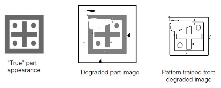
You can train a nearly ideal Composite Model using multiple degraded training images. Composite Model PatMax collects the common features from each image and unites them into a single ideal model. This way, you can filter out noise or other random errors from the training images that would appear in the final Composite Model, as shown in the following figure.
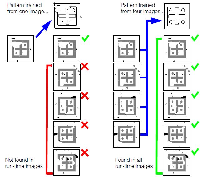
Note that the composite-trained pattern successfully finds the part in both the degraded images used for training, and in newly encountered images.
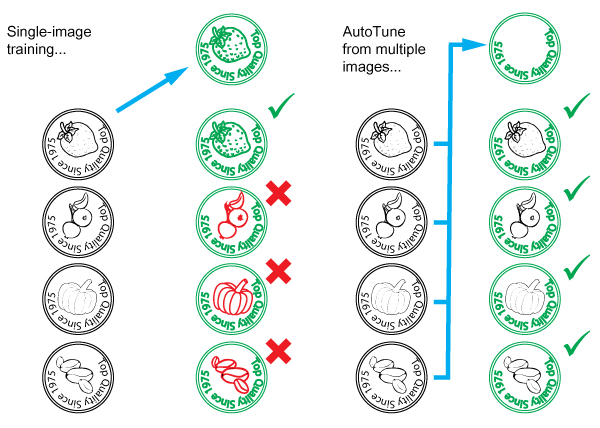
Parts With Variable Features
In some applications, you need to be able to locate and align parts in which certain features may be different in different parts. For example, in the case of a product packaging line, packaging lids may have some features in common (the product name) while other features are different from part to part (the product flavor). The following figure shows how you can use composite PatMax training to create a pattern that includes the features that are the same for all parts while excluding the features that are different from part to part. Composite PatMax training for parts with varying features
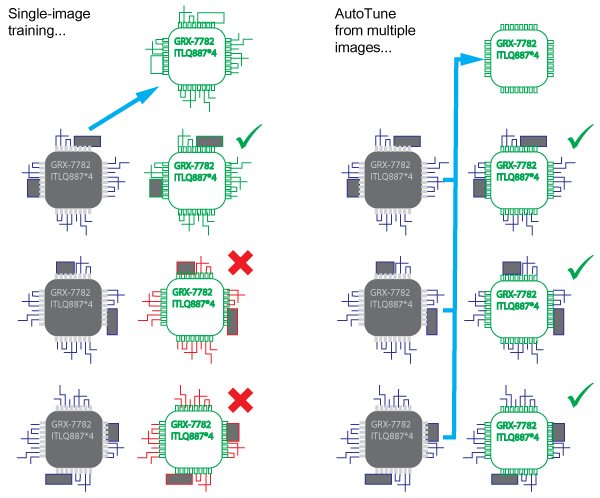
Training with Varying Background
Composite pattern training can also be used to filter out background changes. For example, it allows you to train a pattern that you can use to locate a component at different locations on a printed circuit board, where the background, consisting of electrical connection (tracks and solder) differs at each location. Composite PatMax training is particularly useful when you need to use images of the part already attached to the circuit board for training, as shown in the following figure.
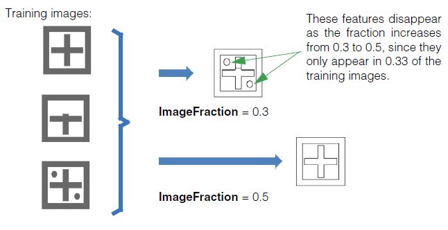
Controlling Composite Training: Minimum Images Fraction
For a feature to be included in a composite pattern, it must be present in at least the minimum images fraction (ImageFraction) of the images.
For example, if you have 4 training images and the minimum images fraction is set to 0.5 (50%), then a feature will have to be present in at least 2 images to be included in the Composite Model. If you have 5 training images and the minimum images fraction is set to 0.5 (50%), then a feature will have to be present in 3 (60% of the) images to exceed the 50% threshold.
The following figure shows the effect of the ImageFraction parameter.
Tuning Elasticity
A feature in one training image is considered to be the same as a feature in another training image if it appears in the "same" location after the two images have been aligned. You can use the distance tolerance (TuningElasticity) to control how far away a matching feature can be, in pixels, and still be considered to be in the "same" location.
For example, with the feature shown below, the capture range would look as follows:
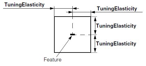
This parameter can be used mainly for speed, reducing the number of correspondences to consider. The internal feature matcher will always prefer closer correspondences. It is far more convenient to specify this value in pels, so that a standard default can be meaningful for many applications.
Composite pattern training may generate synthetic pattern features that do not exactly correspond to the features in any specific training image.
| This tool is not intended for use when the images contain fundamentally different models. In this case, the behavior is still as outlined, but this may produce a subtly unusable model. For example, you could create a single model that is the composite of three unique models, by setting the ImageFraction to approximately 0.25. However, to actually find instances of these models at run-time, the PatMax accept threshold would also have to be around 0.25, which likely would make it impossible to avoid spurious matches. |
Ignoring Polarity
You can ignore the polarity of image features during composite training by setting the The CogPMAlignComposite object's IgnorePolarity property to true.
If you do this, then the trained pattern will contain no polarity information and you must also set the CogPMAlignPattern object's IgnorePolarity property to true.
If you set IgnorePolarity to true for composite training and set the CogPMAlignPattern object's IgnorePolarity property to false, the tool will generate a run-time error. If you wish to consider feature polarity at run time, you must also consider polarity during composite training. |
This section contains the following subsections.
- Shape Training
- Image Training
- All PatMax Training
- 16-bit Image Support
- Large Images
- PatMax Alignment Guidelines
- PatFlex Guidelines
- Run-time Information Strings
- Optimizing PatMax Performance
- Preventing Degenerate Results
- Common Image and Pattern Variations
- PatMax Parameter and Result Summary
This section describes how to train PatMax from a shape description or image, and how to use the trained tool to find likenesses of the pattern in run-time images.
This section contains the following subsections.
- Shape Training Guidelines
- Relating Shapes to Pixels
- Computed Granularity
- The Training Region
- Assigning Weights
Shape training allows you to train PatMax directly from a collection of shape models. Using shape models instead of a training image offers several significant advantages:
- Shape training allows you to define the optimal model to train. For example, if your application needs to locate a fiducial mark but all the fiducial marks encountered by your application have slight pattern variations and defects, then any image you use to train a pattern will include features that are not present in other images. Instead of training a pattern from an acquired image of a fiducial mark, you can create a shape description of an ideal fiducial.
- Shape training is not corrupted by noise.
- Shape training allows you to specify the model origin precisely.
- Shape training allows you to select the portion of the object you need to model more easily than masking a training image.
- Shape training is more effective in those situations where there is a wide range of scale changes present in the run-time images.
- Shape training allows PatMax to explicitly use information about the locations of corners in the model.
- Shape training requires less memory than image training.
When you use shape training, you supply PatMax with a collection of CogShapeModel objects. You can construct this collection using your own code, but in most cases it is simpler to use the Model Maker control supplied with VisionPro. The Model Maker control lets you easily extract shapes from images, draw shapes using a palette of draw tools, and import shapes from VisionPro shape archives and from DXF-format CAD files.
Shape Training Guidelines
In general, you should observe the same guidelines for training patterns from shape models that you do when training from images. The shapes you supply should uniquely identify the pattern you are looking for, and they should not be confusing when considered in the degrees of freedom you will be enabling, as shown in Table 3.
Some other shape training guidelines you should keep in mind are listed below:
- Do not supply shapes with infinite extent (such as lines) for shape training
- Carefully evaluate the granularity limits, as described in the section Computed Granularity.
Relating Shapes to Pixels
Whenever you supply a CogShapeModelCollection to PatMax for shape training, you must provide a way for PatMax to transform the shapes' dimensions into the pixel space of the run-time image. There are two ways that you can do this.
- Each CogShapeModel shape has a selected space name property that explicitly defines the name of the coordinate space in which the shape's dimensions are defined. If you supply an image that has an associated coordinate space tree that includes spaces for all of the supplied shapes, then PatMax can use that shape tree to transform the shapes' dimensions into pixel space. (The pixels of this image are ignored.)
- You can supply a TrainShapeModelsTransform that provides the explicit transformation between all of the supplied CogShapeModel objects and a single pixel space. If you supply this transformation, and select the corresponding training mode, the selected space property of the CogShapeModel objects is ignored.
Computed Granularity
The transformation you supply, whether as a coordinate space tree in an image or an explicit transform, should reflect the actual size of the features. PatMax will automatically compute coarse and fine granularity limits for the shapes you supply, based on their sizes in pixels, and it will use these granularity limits to generate the actual coarse and fine pattern features.
The transformation information you supply, as described in the preceding section, should provide an accurate description of the expected size of the shape models in pixels. If you are training shape models that are much larger or much smaller than the actual sizes of the expected features, PatMax may compute inappropriate granularity values and trained features, which can cause run-time pattern alignment to perform poorly.
Cognex recommends that you size your shape models appropriately before training, by importing or creating them in a calibrated coordinate system. If, for whatever reason, you wish to train scaled shape models, you should carefully evaluate (and change if necessary) the pattern granularity limits generated by PatMax. You can perform this evaluation by examining the trained feature display.
Note: When PatMax computes the granularity limits for a collection of shape models, it may tend to produce too high a coarse limit under some conditions. An excessively high coarse granularity limit can reduce the number of features in the trained pattern below the level required to train the pattern, and it can also potentially cause otherwise acceptable patterns to produce degenerate search results. You can assess the appropriateness of the computed coarse granularity limit by examining PatMax's automatically computed coarse granularity limit for an image-trained pattern where the image corresponds to the shapes you are training.
The Training Region
If you specify a training region for shape training, PatMax will only train features from the shapes (or parts of shapes) that lie within the region.
Note: For shape training, if you specify a region shape other than a rectangle, PatMax will train features that lie within the pixel-aligned bounding box that encloses the region. Also, you cannot specify a training-time mask for shape training.
The dimensions of the input region are interpreted in differently depending on which training mode you are using.
- If you are supplying an image to resolve the selected spaces of each shape model, then the training region is interpreted based on its selected space property (which must be a space defined within the supplied image's coordinate space tree).
- If you supply a TrainShapeModelsTransform, then the input region is always interpreted in the implicit root space (the 'from' space in the TrainShapeModelsTransform transformation).
In all cases, PatMax will only train the shapes or parts of shapes that lie within the input region, as shown in Figure 31
Figure 31. Clipped features
The training region is also used to determine the part of the run-time image that is used to compute the clutter score, as described in the section Clutter Score.
Assigning Weights
This section contains the following subsections.
Each CogShapeModel that you supply to PatMax for shape training has an associated positive or negative weight. These weight values let you weight how different features are used in locating patterns and how the scores of found patterns are computed.
Effective Weight
If a CogShapeModel object includes sub-objects (in this release, only CogGeneralContour objects contain sub-objects), then each sub-object has an effective weight that is equal to the product of the containing shape's weight and the sub-object's weight. If both weights are negative, however, the sub-object's effective weight is zero.
How Weights are Used
All of the shapes (including those with 0 weight) are used for training. At run time, however, shapes are treated differently depending on their effective weight as follows:
- Positive effective weight: Results favor those poses for which the shape matches the image features with high accuracy, although the magnitude of the weight has no effect on accuracy. The shape contributes positively to a PatQuick result score in an amount proportional to the weight, to the shape perimeter, and to the degree of match at the result pose. Image features that match the shape are not considered clutter. Such features instead contribute to the coverage score, but the magnitude of the weight is not used when computing coverage.
- Negative effective weight: Results favor those poses for which the shape does not match the image at all. The shape has no effect on the accuracy of the returned pose. The shape contributes negatively to a PatQuick result score in an amount proportional to the weight, to the shape perimeter, and to the degree of match at the result pose. Image features that match the shape do not contribute to the coverage score. Such features are instead considered clutter.
- Zero effective weight: The shape has no effect on the result pose or its accuracy, and contributes nothing to the PatQuick result score, regardless of degree-of-match. Image features that match the shape do not contribute to the coverage score. Such features are instead considered clutter.
Because the magnitude of a weight does not affect the coverage or clutter scores, a PatMax algorithm result score is only affected by the sign of weights (which determines whether matched features contribute to clutter or coverage, as described above). Therefore, if you wish to experiment with weighting schemes in order to optimize performance with respect to the accept threshold, the PatMax algorithm (if used) should be temporarily disabled. The result score returned will then be the PatQuick result score, which is affected by the magnitudes of the weights. When the PatMax algorithm is again enabled, the PatQuick score will continue to be computed internally and compared to the accept threshold, but it will in general no longer be returned as the score of the results (the PatMax algorithm score will be returned instead).
This section contains the following subsections.
For image training PatMax uses all of the information in the pattern training image you supply. You should avoid including features in the training image that will not be present in the run-time image.
In order to train a pattern from a pattern training image, the image must contain distinguishable features. For best results, you should observe the following guidelines when selecting a training image:
- The pattern should include both coarse and fine features.
-
The pattern should include information that will let PatMax distinguish instances that vary in all enabled degrees of freedom. Table 3 shows examples of patterns that might lead to degenerate results (as described in the section Degenerate Results.
Table 3. Patterns with potentially degenerate results for scale and rotation
Degree of Freedom Potentially confusing patterns Less confusing patterns Scale 
Rotation 

PatMax can return diagnostic information at training time that indicates whether a trained pattern is potentially degenerate in a particular degree of freedom. See Pattern Training Information Strings.
Training Image Coordinate System and Calibration
If the training and run-time images have different coordinate systems or calibrations, then identical patterns in the run-time images will be found at different scale or angle than the trained pattern.
For example, if the same optical and mechanical configurations are used to acquire training-time and run-time images, but the training-time image selected coordinate space units are one half the size of the run-time image selected coordinate space units, the pattern in the run-time image will be found at a scale of 0.50.
You should make sure that the same calibration has been computed for both pattern training and run-time images. If you have not calibrated the pattern training and run-time images, then you should make sure that the optical and mechanical configurations used to acquire the images are the same.
Which Features Are Trained
PatMax considers all of the features contained within the supplied training region, but it may also consider some features from outside the training region. This happens under the following conditions:
- If the pattern training window is close to the edge of the image, features that are closer to the edge of the image than the coarse granularity limit may not be detected. However, if the pattern training window is not close to the edge of the image then it is guaranteed that every feature inside the window is detected, regardless of the coarse granularity setting.
- PatMax can detect features that are outside of the training region if those features are within the coarse granularity limit of the edge of the pattern training window and if they are not within the coarse granularity limit of the edge of the image.
Figure 37 summarizes these two effects.
Figure 32. Features outside the training region can be considered
If the edge of the training region is close to the edge of the training image, then features within the training image might not be trained, as shown in Figure 33.
Figure 33. Features within the training region can be discarded
Because PatMax may train features that are outside the training image, you should take care that no features that are not part of the actual pattern are present in the image near the training region.
Figure 34 shows a case where unwanted features could be trained even though they are outside of the training region.
Figure 34. Extraneous features trained from outside of training region
In general, you should observe the following basic guidelines:
- Do not train a pattern with features that are close to and just inside the training window if the window is close to the edge of the training image; these features may not get included in the trained pattern.
- Always examine the graphic display of the feature boundary points trained as part of a pattern; verify that all the features you expected to be trained are trained and that no extraneous features from outside the training image window are trained.
This section contains the following subsections.
- Pattern Granularity
- Granularity Considerations with Shape Training
- High Sensitivity Mode
- Polarity
- Repeating Patterns
- Auto Edge Threshold
- Pattern Origin
- Pattern Training Information Strings
- PatMax Customization Packs
The following sections apply to both shape training and image training.
Pattern Granularity
For most applications, PatMax does a good job selecting the coarse and fine pattern granularity limits. If you want to override PatMax's granularity limits, you should do so by evaluating the trained features.
Keep in mind that PatMax's strategy in choosing granularity limits is to choose the largest coarse granularity that detects features that can be reliably used to quickly locate the pattern and to choose the smallest fine granularity setting which will reliably and precisely locate the pattern.
The following are examples of when you might decide to override PatMax's settings:
- If the coarse granularity trained feature display is including features that appear not to represent actual feature boundaries, you can try increasing the coarse pattern granularity to exclude the redundant small features. This might increase the alignment speed.
- If the fine granularity trained feature display is including features that are not actually part of the pattern, such as surface texture, you could try increasing the fine pattern granularity to exclude the extraneous small features. This might improve reliability.
- If the fine granularity trained feature display does not include fine features that are part of the pattern, such as fine teeth on a gearwheel, you could try decreasing the fine pattern granularity to include the small pattern features. This might increase accuracy.
You should not attempt to override PatMax's granularity settings without carefully examining the trained feature display. In general, you should choose the granularity that produce trained features that match the features of interest in the image.
Note: When using the PatFlex algorithm, the default granularities are generally smaller due to the need for more detail. If you set your own granularities they will also be generally smaller than those you would set for other algorithms.
Granularity Considerations with Shape Training
As discussed in the section Computed Granularity, if you are using shape training and your shapes are much larger or smaller than the image features they describe, you may need to adjust the granularity limits manually to preserve meaningful features from the pattern.
Note: If you are using the PatFlex algorithm with shape-trained models, you will almost certainly need to set the granularity limits manually. In almost all cases, the granularity limits will need to be reduced from the automatically selected limits. Carefully review the display of trained features to make sure that reasonable features are being trained.
High Sensitivity Mode
PatMax can be run in standard mode or high sensitivity mode. Check your images for contrast and noise. Good quality images should be run in standard mode but if your images have poor contrast or are noisy, you may get better results using high sensitivity mode. Keep in mind however, high sensitivity mode generally requires more execution time than standard mode.
When you use high sensitivity mode you can also set the sensitivity parameter which allows you to specify your image quality. The sensitivity parameter is a number in the range 1.0 through 10.0 where lower numbers specify better quality images and higher numbers specify poor quality images. The default is 2.0. You may need to experiment with this parameter range to see which setting produces the best results for your images. See the discussion in the section High Sensitivity Mode.
Polarity
By default, PatMax will only find matches where the trained pattern polarity and the run-time image pattern polarity are the same. You can specify that PatMax ignore the polarity of patterns in the run-time image. If you specify that PatMax ignore pattern polarity in the run-time image, you will increase the number of potential matches, which can increase image confusion. Also, ignoring pattern polarity reduces the search speed.
Note: You can change the value of this parameter at training time or run time with almost no execution time penalty, although the effect of changing the value can affect search speed.
The default for trained patterns specifies the darker side of a pattern boundary is negative and the lighter side of the boundary is positive. For example, see Figure 35
Figure 35. Enlarged portion of a trained pattern showing default polarity
Repeating Patterns
The PMAlign tool supports a boolean value that you can enable to indicate the pattern you want to train contains elements that repeat.
Auto Edge Threshold
The PMAlign tool uses a default edge threshold value to detect the edges within the patterns you are trying to train and locate in your images. In patterns where the contrast between pattern features can be low, the PMAlign tool can fail to train or locate them as it executes. If necessary you can disable the default value and specify your own minimum grey value between edges.
Pattern Origin
This section contains the following subsections.
As described in the section Generalized Pattern Origin, PatMax lets you specify either a simple pattern origin point or a generalized pattern origin. This section provides guidelines for both origin forms.
Simple Pattern Origin
PatMax returns the position (X-translation and Y-translation) of a found instance of the pattern in a run-time image as the location of the pattern origin in the run-time image's selected space.
When you specify the pattern origin location, keep in mind that if you enable any generalized degree of freedom, instances of the pattern might be reported at a shifted location. Figure 36 shows an example where the transformation between the two patterns is rotation only, but because the an origin at the corner of the pattern training region is used, a translation is reported in addition to the rotation.
Figure 36. Rotation causes apparent translation of pattern origin
Figure 37 shows the effect of specifying a pattern origin at the pattern center.
Figure 37. Pattern rotation with origin at pattern center
In general, you should either
- Set the origin to correspond to a point of interest within the trained pattern.
- Set the origin to be at the center of the trained pattern.
Note: If you are using the PatFlex algorithm, you should make sure to specify an origin that lies within the pattern; the run-time location of an origin outside of the pattern in a deformed image can be very inaccurate.
Generalized Pattern Origin
You specify a generalized pattern origin by supplying a transformation object at training time. PatMax applies this transformation to the training pattern before attempting to locate the pattern in a run-time image, and it returns results relative to the transformed training pattern.
In general, you supply a generalized pattern origin to compensate for known scale or rotation of the training pattern. For more information on using a generalized pattern origin, see the section Generalized Pattern Origin.
Pattern Training Information Strings
When you train a pattern using PatMax, PatMax may provide diagnostic information about the pattern in the form of text strings. Table 4 describes the messages that PatMax can produce at training time.
| Information Strings Messages | Notes |
| 10000: Pattern may contain too few features. | PatMax did not detect enough features to train a reliable pattern. Examine the trained feature display. |
10001: Difficult to choose feature granularity; manual override may be desirable. | Examine the trained feature display. This message is only returned if you have configured PatMax to determine feature granularity automatically. |
10100: Pattern may be less accurate than expected because the training pattern appears blurry. | PatMax trained a pattern, but because the pattern was blurry, the accuracy of alignment results may be reduced. This message is only returned if you are training a pattern using the PatMax algorithm. |
| 10101: Pattern may contain insufficient information to measure DOF reliably. | The trained pattern is potentially confusing in the indicated degree of freedom. See the section Image Training for information on confusing patterns. |
| 10102: Pattern is degenerate. The results will probably be unstable because all of the coarse granularity boundary points have the same direction. | At the coarse granularity limit, all of the feature boundary points have the same orientation. Examine the trained feature display. |
| 10200: Pattern may run slowly due to predominance of fine features; manual override may be possible. | Because of a large number of small features in the pattern, alignment may take more time. Try manually specifying a larger coarse granularity value. |
PatMax Customization Packs
PatMax provides support for loading Cognex-supplied PatMax Customization Packs (PCPs). These PCPs configure PatMax for specific application types. The effect of loading a PCP is to change certain internal PatMax parameters.
Note: You must load a PCP before training a pattern.
This section contains the following subsections.
In addition to CogImage8Grey images, a PMAlign tool can accept images of type CogImage16Range and CogImage16Grey with certain restrictions.
For example, the following table displays the PMAlign tool algorithms and their support for various image types:
| Algorithm | CogImage8Grey | CogImage16Grey | CogImage16Range |
| PatQuick | ✔ | ✔ | ✔ |
| PatMax | ✔ | ✔ | ✔ |
| PatMax High Sensitivity | ✔ | * | * |
| PatFlex | ✔ | * | * |
| Pat Perspective | ✔ | * | * |
Note: Cognex does not support 16-bit image analysis with the PMAlign tool on processors that do not support the SSE4.1 instruction set.
3D Range Images
Images of type CogImage16Range are processed as images of type CogImage16Grey with an additional mask representing the missing pixels. After you create a trained pattern for your range images, Cognex recommends you carefully view the training image with coarse and fine features enabled, to see if there are instances of your pattern surrounded by missing pixels as shown in the following example:
If the edges of the pattern your application must locate can be surrounded by missing pixels, you must add an additional step to create a reliable trained pattern. Specifically, you must remove the missing pixels using either the Missing Pixel operator of the One Image Edit Control or you must convert the CogImage16Range image into an image of type CogImage16Grey using the PixelMap Edit Control.
For details on enabling coarse and fine features in the image of your trained pattern, see the PMAlign Edit Control.
Limitations
Be aware of the following limitations of the PMAlign tool regarding 16-bit image types:
- The Autotune feature does not support 16-bit images.
- The tool does not support training a 16-bit pattern and then using it on an 8-bit image.
- Although images of type CogImage16Range represent 3D entities, the results returned by a PMAlign tool are in 2D coordinate spaces.
The PMAlign tool cannot function on any portion of an image where any pixel has a coordinate value (along either the x-axis or y-axis) that exceeds 32767. This limitation includes the area of the image you use to train a pattern and the image itself, as well as any region of interest you might specify. If necessary, you can pass the input image to a One Image Tool with no image-processing operations. A One Image Tool can be configured to simply generate a smaller output image where no pixel has a coordinate value of 32767, and then this image can be used as the input image to the PMAlign tool.
This section contains the following subsections.
- Degrees of Freedom
- Accept Threshold
- Number to Find
- Elasticity
- Scoring Clutter
- Extreme Scale Changes
- Patterns Trained From Acquired Images
This section provides an overview of the parameters you specify when you use PatMax to search for a model in a run-time image.
In general, you should keep the following basic guideline in mind: The more specific the information that you can provide about the objects in the run-time image, the faster PatMax will operate. Each of the following items increases the size of the run-time space and increases the amount of time PatMax requires to find objects:
- Increased number of enabled degrees of freedom
- Larger zones for enabled degrees of freedom
- Decreased accept threshold
Constraining the overall size of the run-time space can also tend to reduce the likelihood that PatMax will encounter degenerate results.
Degrees of Freedom
For each of the possible degrees of freedom other than location you must either specify a nominal value, or a range of acceptable values. PatMax only searches within the combination of nominal and ranges that you specify.
In general, you should enable a degree of freedom and specify a zone if you expect patterns to vary in the degree of freedom or if you need to measure the degree of freedom.
Accept Threshold
The higher an accept threshold you specify, the faster PatMax will be able to perform an alignment. You should establish the accept threshold for your application by running a series of test alignments. Select an accept threshold that is slightly below the lowest score that an actual instance of the pattern receives.
A good starting point for the accept threshold is 0.5.
Number to Find
You should specify the number of results that you expect the run-time image to contain. Because of PatMax's ability to find transformed versions of the trained pattern, run-time images may contain many more instances of a pattern than you might expect.
For most alignment applications, you should specify 1.
Elasticity
Unless you expect pattern variations that cannot be described using a linear transformation, you should specify a value of 0.0 for elasticity.
If you experience alignment failures or unstable score results, you can begin experimenting with low elasticity values. In general, you should specify the lowest elasticity value that provides stable and consistent alignment results.
If you are expecting significant nonlinear pattern deformation, you should use the PatFlex algorithm.
Scoring Clutter
If objects will appear on a variety of backgrounds, you should specify that PatMax ignore clutter when scoring objects.
If your application is an alignment application in which the background does not change, you should specify that PatMax consider clutter when scoring objects.
If you are using shape training because of extraneous features in your images, you should probably ignore clutter.
Extreme Scale Changes
PatMax can find patterns at a wide range of scale changes between the trained model and the run-time images. Increasing scale changes in the run-time image can affect PatMax performance and accuracy. You should keep in mind the following points about the effect of scale changes on PatMax:
- The presence or absence of scale change itself has no effect on PatMax speed or accuracy.
- The effect of increasing scale change is extremely image-dependent.
- If you are searching for extremely small, simple patterns, train a larger pattern, preferably using a shape description.
As the size of the scale change between the trained pattern and the run-time pattern instance becomes very large, several factors come into play. These factors are different depending on whether your application uses patterns trained from acquired images or patterns trained from shape descriptions.
Note: All of the numbers discussed in this section are approximate. The specific performance of PatMax and the effect of specific scale changes is dependent on the content of the images used for pattern training and pattern location. You should conduct your own tests using a range of images to determine the best PatMax parameter settings for your application.
Patterns Trained From Acquired Images
As the size of scale change between the trained pattern and the run-time pattern increases, PatMax's performance can begin to degrade. In general, scale changes below 10% to 20% have no effect on PatMax's ability to discriminate patterns within a run-time image, and no effect on PatMax's ability to locate patterns with ultrahigh precision (better than 0.10 pixels).
As scale change increases above 10% to 20%, some applications will experience a reduction in accuracy levels.
At extremely large scale changes (greater than a factor of 2), some applications will experience problems discriminating patterns in run-time image.
PatMax is more likely to be able to successfully handle large scale changes when the overall shape of the trained pattern does not change at different granularities. Figure 38 shows an example of a pattern whose shape changes at different granularities.
Figure 38. Pattern shape change with granularity change
The pattern shown in Figure 38 may be more difficult for PatMax to find at extreme scale change.
The pattern shown in Figure 39 has the same shape at different granularities. This pattern may tend to work better with extreme scale changes.
Figure 39. No pattern shape change with granularity change
Note: If the run-time pattern is less than about one third the size of the trained pattern, the coverage score it receives will be reduced. This reduced coverage score, in turn, lowers the overall score received by the pattern, even though the shape of the pattern may be a good match with the trained pattern.
This section contains the following subsections.
- Use Appropriate Image Content
- Limit the Number of Control Points
- Limit Degrees of Freedom and Deformation Rate
You should only use the PatFlex algorithm under the following conditions:
- You expect significant nonlinear deformation of the trained pattern in your run-time images.
- You wish to produce an undeformed version of the run-time image.
The guidelines in this section can help you use the PatFlex algorithm effectively.
Use Appropriate Image Content
PatFlex works best when used to locate patterns with the following characteristics:
- A range of feature sizes
- A variety of feature shapes and orientations
You should avoid using PatFlex with patterns that are dominated by regular arrangements of straight lines.
Limit the Number of Control Points
Increasing the number of control points tends to increase the amount of time required to refine a PatFlex result. In most cases, PatFlex will return accurate results if you specify six control points in both the X- and Y-direction.
Limit Degrees of Freedom and Deformation Rate
As is the case with the standard PatMax and PatQuick algorithms, increasing the number of enabled degrees of freedom or the zone size for any enabled degree of freedom increases the amount of time required for the search. The maximum deformation rate (specified at run time) has a similar effect on performance; the larger the maximum deformation rate, the longer the search may take.
Specifying a larger expected deformation rate (at training time) increase training time but has only a small effect on search time.
When you search for a pattern using PatMax, PatMax may provide diagnostic information about the pattern in the form of text strings. To check for this information call one of the following functions after the search to read any text strings the tool writes.
Table 5 describes the messages that PatMax can produce at run time.
| Information Strings Messages | Notes |
20300: N results were discarded due to contrast threshold. The score of the best discarded result was S. | PatMax discarded one or more patterns because their contrast was below the contrast threshold you specified for the alignment. You may be able to see these results by lowering the contrast threshold. Note that the score value included in this message is approximate, since the result was excluded from processing before the final score was computed. |
20301: N results were discarded due to proximity to stronger results. The score of the best discarded result was S. | PatMax discarded one or more patterns because they overlapped other better matches. You may be able to see these results by adjusting the relevant overlap threshold. Note that the score value included in this message is approximate, since the result was excluded from processing before the final score was computed. |
20302: N results were discarded due to excess clutter. The score of the best discarded result was S. | PatMax discarded one or more patterns because they had too many extraneous features. You may be able to see these results by ignoring clutter when scoring. This message is only returned if you have configured PatMax to consider clutter when scoring pattern instances. |
20303: Degenerate system detected for this result. | This PatMax result was one of several degenerate results. You can only obtain this message by requesting the diagnostic message for an individual result, not for an entire set of results. |
By configuring the PatMax alignment parameters appropriately, you can achieve the optimum balance between execution speed and robustness for your application. Table 6 lists the factors that affect PatMax execution speed.
| Factor | Effect | Notes |
| Additional degrees of freedom | Each additional degree of freedom you enable increases the required alignment time. | Only enable a degree of freedom if
|
| Increasing zone size for a degree of freedom | The larger the range of values you specify for a degree of freedom, the longer a PatMax alignment requires. The increase in execution time might not be linearly related to the increase in zone size. | PatMax might return pattern instances that are slightly outside of the range you specify. PatMax only does this if it can do so without increasing the alignment time or decreasing the result accuracy. |
| Decreasing accept threshold | The lower the accept threshold you specify, the longer a PatMax alignment requires. | You should determine the accept threshold using test alignments. |
| Number of instances to look for | The more instances you tell PatMax to look for, the longer the alignment may take. | Increasing the number of instances can increase the number of potential matches that PatMax must evaluate. |
| Run-time area | The larger the run-time area, the longer the alignment takes. | Depending on your application, reduce the size of the run-time area as much as possible. |
| Pattern size | In general, the larger the size of the trained pattern (in pixels), the faster alignments will run. | Select a training pattern that includes as many pattern features as possible. |
| Image confusion | The more confusing the image, the longer alignments will take. | Train patterns that are unique within run-time images. |
| Coarse granularity | In general, the larger the coarse granularity limit, the faster alignments will run. | Use caution in manually changing the coarse granularity limit. |
| High sensitivity mode | Produces better results for low contrast and noisy images. | Tune the degree of sensitivity with the sensitivity parameter. |
| Sensitivity parameter | Specifies the amount of pattern noise rejection for high sensitivity mode. | Use the default value for most applications. |
You can reduce the likelihood that PatMax will detect degenerate results by following these guidelines:
- Make sure your pattern offers distinct information in all the degrees of freedom you enable in your alignment, as described in the section Image Training.
- Only enable the degrees of freedom that will actually change from run-time image to run-time image. If the value for a degree of freedom will be the same for all images, specify a nominal value for that degree of freedom.
- Make sure that your run-time image does not contain extraneous features.
- Obtain the information strings for each pattern you train and for each alignment you perform. See Pattern Training Information Strings and Run-time Information Strings.
Table 7 summarizes common image variations, the possible effect of these variations on PatMax, and recommended approaches for handling these variations.
| Variation | Possible Effect | Possible Remedy |
| Typical video noise | None | |
Severe video noise |
|
|
Feature polarity reversal |
|
|
Extremely low image contrast |
|
|
Extremely high image contrast (camera saturation) |
|
|
| Changes in shading | None | |
Rotation or size changes |
|
|
Aspect ratio changes |
|
|
Shape changes (change in geometrical arrangement of pattern features) |
|
|
Missing features |
|
|
Extra features |
|
|
Table 8 summarizes the parameters that you supply to PatMax and the results that PatMax returns to you. Different parameters and results are used and returned for training and alignment.
| Type | Item | Notes |
Training parameters | Model origin | Location in pattern model to use when returning result locations in run-time images Can be set at run time with minimal time penalty. |
| Training image | The pattern of interest | |
| Training mode | Whether to train using image pixels or shape models | |
Elasticity | Amount of tolerance (in pixels) for nonlinear geometric change in feature location Can be set at run time with minimal time penalty. | |
Polarity tolerance | Either consider or ignore the polarity information in patterns in the run-time image Can be set at run time with minimal time penalty. | |
Feature granularity | Controls the size of features that make up a trained pattern. Must set before training. Do not set manually for most applications. | |
| High sensitivity mode | Use standard mode for normal images, high sensitivity mode for noisy or low contrast images. | |
| Sensitivity parameter | Use the default value for most applications. | |
| Mask image | Excludes parts of training image from pattern. | |
| Repeating patterns | Allows for repeating elements in the pattern you want to train. | |
| Auto edge threshold | Disables the automatic edge threshold in favor of another value your images require. | |
| Alignment parameters | Enabled degrees of freedom | Only enabled transformations are measured |
| Nominal transformation value(s) and zone(s) | For each non-enabled degree of freedom, specify a nominal value. For each enabled degree of freedom, specify a range of values (zone). | |
| Number of results | The number of instances of the pattern you expect PatMax to find in the run-time image | |
| Contrast threshold | The minimum contrast value for pattern instances | |
| Score using clutter | Whether or not to consider the effect of extraneous features on pattern instance score | |
| Accept threshold | Threshold for considering an instance of the pattern as valid | |
| Mask image | Exclude parts of run-time image from consideration | |
| Timeout | Maximum amount of run time PatMax use | |
| Coarse Accept threshold | Change the default value the tool uses to determine the coarse features of your pattern in run-time images, which will vary the number of potential candidates the tool will use to refine the search. | |
| Alignment results | Location | Location of each instance |
| Pose | Description of how instance is mapped from trained pattern to run-time pattern instance | |
| Scores | Indication of degree of fit |