This topic contains the following sections.
This topic describes height measurement with the VisionPro Height Calculator Tool using range images acquired from a Cognex 3D displacement sensor. The sensor produces range images that contain 16-bit pixel values, where each pixel value represents the distance from a reference plane to the object’s surface. The Height Calculator Tool computes the height of such a range image, or a specified subset of pixels in such a range image, relative to a base plane.
For the theory of range images, acquired from displacement sensors, see the Working with 3D Range Images topic. For information on setting up acquisition with your displacement sensor, see the Getting Started topic. For detailed information on range image acquisition, see the Acquiring Images from a DS900 Series Sensor and Acquiring Images from a DS1000 Series Sensor topics. For advanced range image acquisition details, including coordinate spaces related to range images, see the Range Image Coordinate Spaces and Associated Parameters topic. For hardware-related information (such as mounting and physical product features) and further product details, see the DS900 Quick Reference Guide, DS1000 Quick Reference Guide, and the DS1000 Technical Reference Manual.
Figure 1 shows a small block sitting on top of a larger block that in turn rests on a conveyor belt. In this situation, a user might want to compute the combined height of the two blocks (i.e. the distance from the top of the top block to the conveyor belt) or, alternatively, just the height of the top block (i.e. the distance from the top of the top block to the top of the lower block). The Height Calculator Tool will allow either of these use cases by letting the user specify a base plane; the computed height will be the distance from that plane to the 3D surface specified by the range image. Thus, the combined height of the two blocks could be computed by using the plane of the conveyor belt as the base plane, and the height of just the top block could be computed by using the plane of the top surface of the lower block as the base plane.
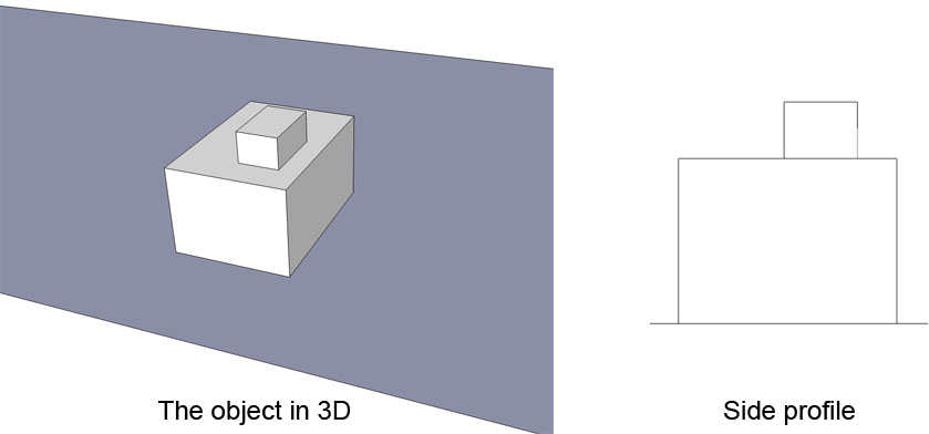
Figure 2 below shows a similar situation with two blocks, except that in this case the lower block is a wedge. The height of just the top block can still be computed by using the plane of the top surface of the lower block as the base plane, but in this case that base plane is tilted rather than horizontal.
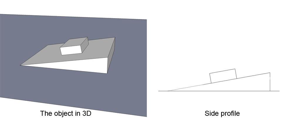
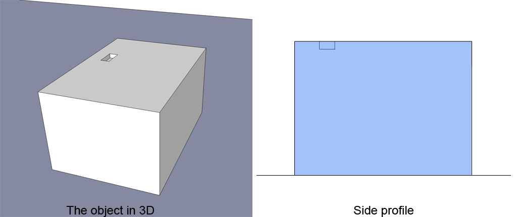
Figure 3 shows a single block with a shallow divot in the top surface of the block. Such a divot might be a machined hole, or it might be a defect. The height (or depth) of the divot can be computed by using the plane of the top surface of the block as the base plane, but in this case the height below the base plane to the range image surface is measured.
The Height Calculator Tool will allow any of the use cases above by letting the user specify a base plane.
Since the most typical use of the Height Calculator Tool is expected to be computing the height of a part above a base plane (e.g. the conveyor belt that the part is sitting on), the user will need to specify that base plane. For example, the user might determine that plane from field calibration (e.g. perhaps the conveyor belt is calibrated so that its surface lies on the z=0 plane) or from the Plane Estimator tool. The height of a single pixel in a range image above a base plane is defined as the signed distance from the center of that pixel to the plane measured perpendicular to the plane.
For more information on this, see the Calculating the Volume of Features in 3D Images topic.
This section contains the following subsections.
Computing a single height value for a set of range image pixels (e.g. an entire range image or a region of a range image) requires specifying a particular statistic to use to combine the heights of the individual range image pixels:
- minimum: Minimum
- maximum: Maximum
- median: Median
- mean: Mean
- mean plus some multiple of the standard deviation: MeanPlusStdDevMult
- low percentage tail: LowTail
- or high percentage tail: HighTail.
For some applications, the user might want height values at or "below" the plane to be excluded entirely from the statistics, while in other applications such values are treated as negative heights. For example, in the case of the two blocks shown in Figures 1 and 2, if we want to compute the height of just the top block and thus use the top surface of the lower block as the base plane, and if we want to use the mean to compute the height then we would not want any part of the lower block included in computing the mean height.
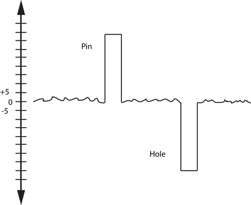
Thus, the user is allowed to specify which individual range image pixel height values should be used in computing the overall height. In the example above, the user would include only positive heights in the computation. Figure 5 below shows another example, in which there is a bumpy surface with a pin sticking up from the surface and a hole sunk into the surface. The bumps in the surface, which the user wants to ignore, all have heights in the range (-5, +5). Thus the user could compute the height of just the pin using a height range that included only values greater than or equal to 5. Similarly, the user could compute the depth of just the hole using a height range that included only values less than or equal to -5. The user could even simultaneously measure the heights of both the pin and the hole, by excluding the height range between -5 and 5.
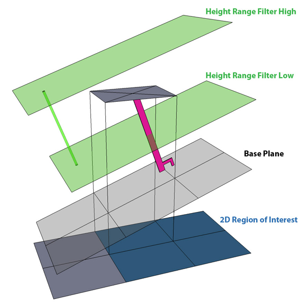
A 3D plane divides space into two regions, one on either side of the plane. For the Height tool, the user needs to specify which side of the plane should be considered above the plane; points that are above the plane have positive height, while points below the plane have negative height.
A straightforward way to specify a side of the plane is to use the plane's normal; one side of the plane consists of the points pointed to by the plane's normal, and the other side consists of the points pointed to by the negative of the plane's normal. More precisely, any point in space can be represented as the nearest point on the plane plus a multiple of the plane's normal vector: p = pclosest + t * planeNormal
| By default, the plane normal is always in the positive z direction in real world coordinates. |
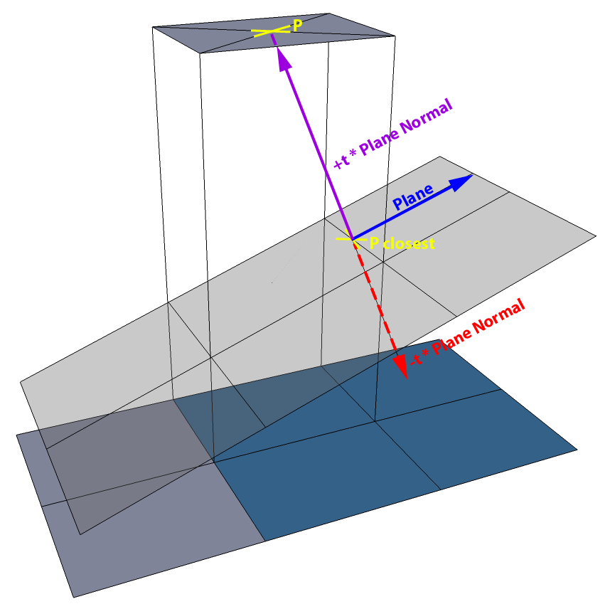
All of the points for which t is positive are on one side of the plane, all of the points for which t is negative are on the other side of the plane, and all of the points for which t is zero are on the plane. We will refer to the side of the plane where t is positive as the side of "increasing plane normal" and to the side of the plane where t is negative as the side of "decreasing plane normal".
The other way to determine the sides of a plane is thinking in terms of the Z values - and this is the more likely one. Users will probably tend to think of one side as being "above" the plane and the other as "below" the plane all expressed by the Z values the range image has. More precisely, at any given 2D (x,y) coordinate on a non-vertical plane, the plane has some z value, and any other point in space at that (x, y) value can be represented as follows: z(x,y) = zplane(x,y) + u
All of the points for which u is positive are on one side of the plane, all of the points for which u is negative are on the other side of the plane, and all of the points for which u is zero are on the plane. We will refer to the side of the plane where u is positive as the side of "increasing z" and to the side of the plane where u is negative as the side of "decreasing z".
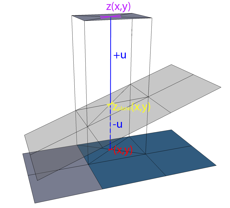
| It is not possible to use z values to distinguish between the two sides of a plane that is vertical, i.e. whose normal vector has a z component of zero. Thus, functions that allow specifying the side of a plane using z values will typically return an error if the plane is vertical. |
- The height is reported in units defined in the Input Image’s SelectedSpaceName3D, e.g. in mm.
- The range image may have non-visible (or "missing") pixels. Such pixels do not contribute to height measurement and are excluded from the reported height statistics.
- In the context of the Height Calculator, "Used" pixels are the range image pixels that contribute to the height calculation. A range image pixel is "Used" to calculate the height if:
- It is inside the 2D input Region of the tool.
- It is marked "care" in the optional InputImageMask provided as part of the RunParams.
- It is marked as "visible pixel" in the visible pixel mask of the InputImage. The visible pixel mask can be accessed by calling GetMaskData on the range image.
- Its height falls within the valid height range configured in the height tool's run parameters. See HeightRangeFilterEnabled.
- The floating display displays the height values in Sensor 3D Space regardless to the base plane.