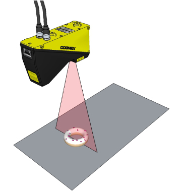
Cognex 3D displacement sensors return information about three-dimensional objects that cannot be easily generated by cameras that acquire two-dimensional images. To generate a 3D range image containing the data, a sensor uses a laser-stripe illuminator to perform surface profiling:
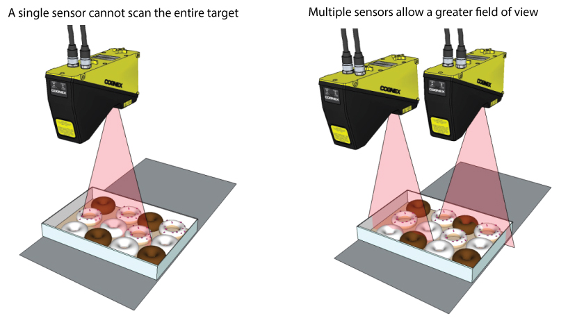
For some vision applications, however, the target is too large for a single 3D sensor to scan it successfully. Multiple 3D sensors can be combined to scan the entire surface area:
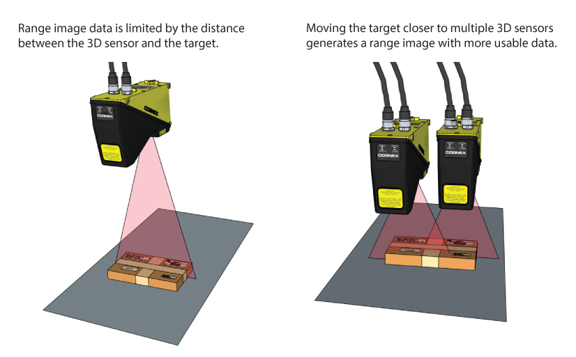
In other cases, the dimensions of a target require that it be located at the far edge of the field of view, reducing the accuracy of the resulting range image data. When your application must analyze the RangeWithGrey range image with 2D vision tools, such as the ID Tool or the OCRMax Tool, multiple 3D sensors can be combined to generate a range image with more accurate grey-scale information.
To combine two or more simultaneous scans, VisionPro must perform image stitching, a process that combines a set of individual range images into a single, merged range image. Successful image stitching requires that the field of view for all participating sensors be calibrated so that they share a unified 3D coordinate space.
This topic contains the following sections.
This section contains the following subsections.
In order to generate a unified 3D coordinate space for use between multiple 3D sensors scanning a single scene, you must perform a field calibration and generate calibration data that can be applied to subsequent 3D scans prior to image stitching.
The process of field calibration can be summarized as follows:
- Multiple 3D sensors capture simultaneous range images of a known calibration target as it makes repeated passes in the field of view.
- VisionPro analyzes the input images to measure the motion of the target and its pose in 3D physical space.
- VisionPro constructs a mathematical transform to map points in each incoming image into a unified 3D coordinate space common to all participating 3D sensors.
- VisionPro saves the calibration data for you to apply to image acquisition sources in your deployed applications.
Once your 3D sensors have been field calibrated, you can create a vision application that collects range images from the same array of 3D sensors and make them available to the CogVisionDataStitch tool, which accepts multiple input range images and generates a single output range image. Stitched range images contain height-profile information that can be analyzed by other 3D vision tools to generate information about a planar surface, to generate height or volume calculation, or to analyze a cross-section of the object. A range image can also be passed to any number of traditional vision tools to perform tasks such as pattern matching or optical character recognition.
In addition, you can perform field calibration on a single sensor and generate images in your deployed application that can be measured with greater accuracy using 2D and 3D vision tools.
This section contains the following subsections.
In order to generate valid calibration data, the field calibration process imposes the following requirements:
64-bit OS support only
Cognex does not support using the field calibration application and the CogVisionDataStich tool on a 32-bit OS.
All participating 3D sensors must have the following in common:
The same 3D sensor model
For example, they must all be Cognex DS1050 sensors, DS1101 sensors, or so on. You cannot mix sensors of different types.
Must be rigidly mounted with respect to the production environment and to each other.
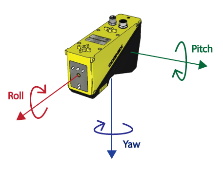
Field Calibration supports a minimum amount of roll, pitch and yaw for any 3D sensor with respect to your production environment and to each other:
- Roll and Pitch: 5 degrees
- Yaw: 10 degrees
Must be configured for your network
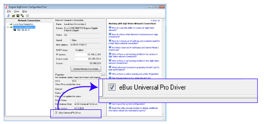
Configure all of your Cognex GigE Vision cameras through the Cognex GigE Vision Configurator, lauched from the Start menu. Set the maximum Jumbo frame and receive buffer size to their maximum values. In addition, ensure that the eBus Universal Pro Driver checkox is enabled, as shown:
Connected to the same quadrature encoder signal.
While Cognex 3D sensors generally support single-channel and quadrature encoders, the field calibration application does not support single-channel encoders.
See the topic Acquisition Triggering for details on how to share an encoder signal between multiple 3D sensors.
- The calibration target moves in a straight line at a constant velocity.
You use a Cognex-supplied calibration target.
VisionPro uses the known geometry of the calibration target to generate the calibration transform.
Once calibrated, you cannot modify any of the following without performing another field calibration.
- The position of the 3D sensors relative to each other or to the motion system
- The encoder type, direction, and number of encoder channels
- The linkage between the motion mechanism and encoder (wheel diameter, for example) which will affect the distance moved for each cycle of the encoder signal
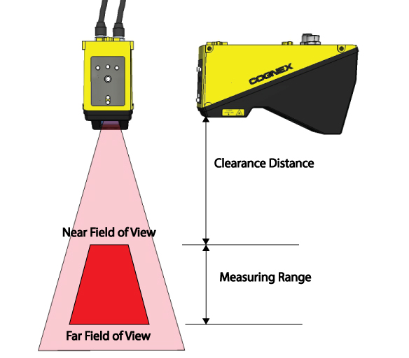
VisionPro supports field calibration for the following Cognex Displacement Sensors:
| Sensor Model | Maximum Number of Sensors | Clearance Distance (mm) | Near Field of View (mm) | Far Field of View (mm) | Measurement Range (mm) |
| DS925B | 4 | 53.5 | 23.4 | 29.1 | 25 |
| DS1050 | 4 | 87 | 43 | 79 | 76 |
| DS1101 | 8 | 136 | 64 | 162 | 220 |
| DS1300 | 8 | 181 | 90 | 410 | 725 |
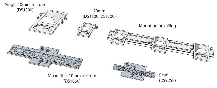
To perform a field calibration on one or more 3D sensors, you must use a Cognex-supplied calibration target. The target consists primarily of a frustum, a feature exhibiting six different planes with eight intersecting points and a unique numerical inscription.
There are two types of frustums:
- Smaller monolithic frustums to support the high-accuracy DS925 and DS1050 3D sensors
- Non-monolithic larger frustums to support the DS1000 series models with larger fields of view
The following table lists all the calibration target models:
| Model | Monolithic | Topside (mm) | Clearance (mm) | Height (mm) |
| TS5 | Yes | 5 | 15.6 | 0.875 |
| TS10 | Yes | 10 | 31.3 | 2 |
| TS20 | No | 20 | 62.5 | 10 |
| TS40 | No | 40 | 125 | 20 |
The type and size of the target you choose depends on the particular 3D sensor model you are using.
| Sensor Model | FoV (mm) | TS5 | TS10 | TS20 | TS40 |
| DS925B | 22 - 28 | ✔ | |||
| DS1050R | 43 - 79 | ✔ | ✔ | ||
| DS1101R | 43 - 79 | ✔ | ✔ | ||
| DS1300 | 90 - 410 | ✔ | ✔ |
Contact your Cognex sales representative for choosing the right calibration target for your application. The targets arrive in a kit that requires some assembly depending on which 3D sensors you use. Refer to the document DS Field Calibration Target Setup that arrives with the kit, or refer to the file FieldCalibration_WiringAndTargetSetup.pdf available from the VisionPro support web site.
Regardless of whether you use monolithic or non-monolithic calibration targets, Cognex recommends you secure your target to a mounting plate attached to the motion system, as highlighted in the following figure:
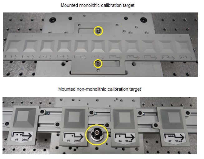
Cognex recommends your mounting plate include additional mounting holes corresponding to each of the anticipated calibration target poses. Inn addition, mount the target so that it is located approximately at same height as the top of the object you want to analyze as it passes through the field of view for the 3D sensor array.
Cognex recommends you use one frustum for each 3D sensor you want to calibrate, and mount the frustums to the railing so that they are spaced to match the spacing of the 3D sensors, as shown:
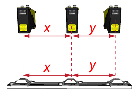
In addition, label the frustums randomly to make it more difficult to accidentally calibrate using one target and validate with another if you use multiple calibration targets in your production environment.
The DS900 sensor, with its narrow field of view, can be mounted in very close proximity to other DS900 sensors.
If you are using the DS1000 series sensors, however, you must consider the spacing between adjacent sensors both along the field of view and along the vector of motion. Depending on the width of the field of view you require and the height of the object you want to analyze, you must mount your 3D sensors while considering the spatial staggering and spatial displacement you need to acquire reliable scans of the objects you want to analyze.
This section contains the following subsections.
Your 3D sensor configuration must have enough spatial displacement so that the width of the combined working sections from all the 3D sensors is equal to or less than the field of view at the height of objects you want to analyze. The following figure illustrates spatial displacement:
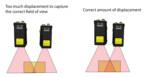
The necessary displacement depends on the size of the detection zone within the working section that you need for your application. The help file for the Field Calibration application provides additional guidance for spatial displacement.
To prevent overlapping lasers being detected by coplanar 3D sensors, Cognex recommends you physically position the 3D sensors such that their lasers are not visible in the desired working section of adjacent sensors by mounting them with some of amount of stagger along the direction of motion, as illustrated in the following figure:
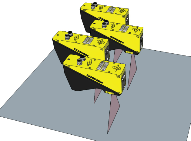
The necessary stagger depends on the size of the detection zone within the working section that you need for your application. The help file for the Field Calibration application provides a formula and additional guidance for spatial staggering.
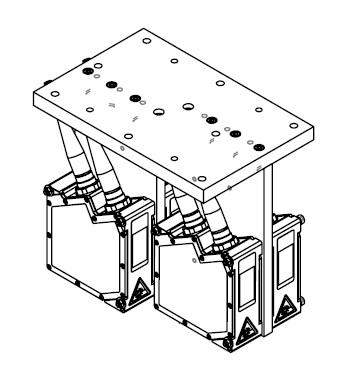
Although the DS900 does not have the same requirements for spatial displacement and spatial stagger as the DS1000 series, several precision mounting options for the DS900 are available. Contact your Cognex sales representative for more information. The following figure shows a drawing of the multi-sensor bracket:
Perform field calibration using the DS Field Calibrator application, installed as part of VisionPro and available from the Start menu. The utilty displays a graphical user interface that walks you through the field calibration process:
The application performs the following tasks for the 3D sensors in your production environment:
Setup: Specify which 3D sensors you want to calibrate and allow the application to determine the best acquisition parameters for locating the calibration target in repeated scans.
You must perform the setup phase again if you change 3D sensor or other acquisition parameters in your production environment.
Calibrate: Scan the calibration target as needed and generate a mathematical transform that allows you to generate a single image with scans from separate 3D sensors.
The application saves the calibration file for you to use in the acquisition source for each 3D sensor.
Validate: Compare an existing calibration to the current orientation of the 3D sensors.
Cognex recommends you perform a validation immediately after a calibration.
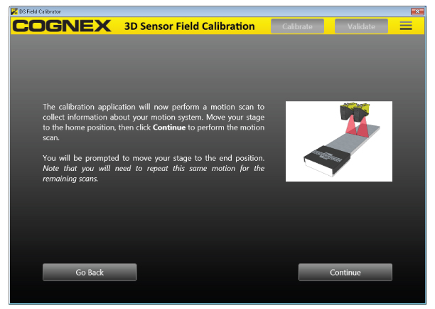
As you use the application you will need to perform vertical and horizontal scans of your calibration target, as shown in the following figure:
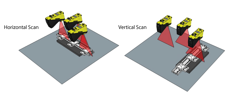
In a vertical scan, the target is passed under the field of view of the 3D sensor, and the sensor must detect N frustums if calibrating N sensors. Cognex recommends you allow the entire target to pass under the sensor to simplify and reduce re-scans that might be required by the calibration process.
In a horizontal scan, one complete frustum must be seen by each sensor and the ID of that frustum must have been detected in a vertical scan.
This section contains the following subsections.
- Calibration Modes
- Recalibrating
- Required Security
- Motion Stage Plug-In
- Calibration Result
- Single Sensor Calibration
- Validation
The application offers three types of calibration modes, with each mode requiring a different number of scans:
| Calibration Accuracy Mode | Number of Vertical Scans | Number of Horizontal Scans |
| Minimum | 1 | 1 |
| Typical | Number of Sensors | 3 |
| Accurate | Number of Sensors * 2 | Number of Sensors + 2 |
Cognex recommends you experiment with Typical mode for most applications, and choose Accurate mode if necessary. Cognex recommends Minimum mode for demonstration purposes or the simplest of objects with little detail.
You must generate new calibration data when any of the following change in your production environment:
- You replace any 3D sensor in your configuration.
- The position and orientation of any 3D sensor changes.
- You modify the distance between any or all 3D sensors and your motion system.
To run the DS Field Calibrator application, your VisionPro security key must support the required VisionPro licenses. See the topic Using VisionPro Security Keys for details on how VisionPro ensures the software is properly licensed. Contact your Cognex sales representative for more information.
The Field Calibration application can interface directly with a motion stage through a motion controller plug-in that you specify. You must write and compile a C# assembly in Visual Studio based on a supplied framework.
Your VisionPro installation includes a sample C# project in %VPRO_ROOT%\samples\Programming\DSFieldCalibration\MotionControllerPlugin\C#. The sample project contains comment blocks that can be uncommented.
A complete calibration produces a mathematical transform for use with the CogVisionDataStitch tool, and saves this transform in an external file. Be aware that the only way to verify that the calibration result is useful is to perform a validation, as described in the section Validation.
As you configure your acquisition source for each 3D sensor you want to use to generate a single stitched image, you specify the same calibration file. See the topic DS1000 Acquisition Using Field Calibration for an example.
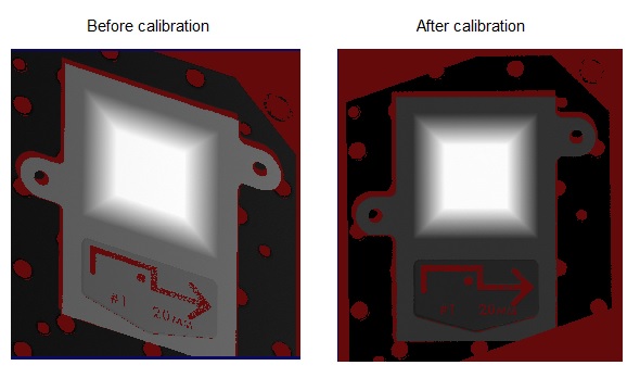
You can use the Field Calibration application to generate calibration data for a single 3D sensor. Calibrating a single 3D sensor removes any apparent skew and allows you to render a corrected output image for more accurate 2D and 3D measurements.
The following figure shows 3D range images of a frustum from a single sensor before and after calibration:
If your application acquires RangeWithGrey images with field calibration enabled, VisionPro adds a border of missing pixels around and between the CogImage16Range and CogImage16Grey halves of the combined image:
The Field Calibration application allows you to validate an existing calibration by acquiring a scan of your calibration target and comparing those results to the calibration data previously generated. Perform the validation by presenting the calibration target for a horizontal scan by all 3D sensors. Each 3D sensor must detect at least a single frustum with a unique ID.
Follow the prompts displayed by the application to perform a validation scan. Be aware of the following requirements during validation:
- You must use the same calibration target during validation as you used during calibration.
- The calibration target must be as free as possible of dirt, dust and fingerprints, which will all affect the calibration results.
- The calibration target must be scanned at the same height during validation as it was during calibration.
The validation process produces a score between 1 - 100 to characterize how well the existing calibration data compares to the found geometry of the calibration target in the validation scan. The higher the score, the closer the validation scan matches the expected geometry of the calibration target, and by extension your production environment. The validation score depends on an array of factors including the speed of your motion system, the distance between the 3D sensors and your motion plane, your encoder settings, and more.
Cognex strongly recommends you perform a validation immediately after calibration, to learn how well the configuration of 3D sensors operating in your production environment can return accurate measurements in the 3D space defined by your motion system. For some environments, the score will be close to 100. For other environments, a validation performed immediately after calibration will produce a lesser score. Initial scores below 100 might reflect the high rate of speed of your motion system, current exposure settings, or other factors. You might choose to alter some of the acquisition settings of the 3D sensor or modify your production environment and perform a new calibration/validation to see if you can generate a higher validation score.
As your vision application operates, Cognex recommends you perform a periodic validation and compare the latest score against the score generated immediately after the initial calibration. As the validation score decreases from its initial score, the more your 3D sensor array will generate output images with less accuracy compared to the actual object under inspection. All multi-3D sensor applications require recalibration periodically.
How often you perform a validation depends on your production environment. Depending on the accuracy your vision application requires, you might choose to perform a validation after an interval of days or weeks.