This topic contains the following sections.
- Supported Coordinate Spaces for Range Image Rendering
- Acquisition Setup Steps with Field Calibration for One Sensor - Summary
- Acquisition Setup Steps with Field Calibration for One Sensor
- Acquisition Setup with Field Calibration Using Multiple Sensors
Use field calibration to render a range image from one or more 3D sensors in the coordinate space you choose, to automatically detect and calibrate sensor physical setup and compensate for sensor mounting inaccuracies to render a field-calibration-corrected (deskewed) range image. The range image can be acquired and rendered from a single displacement sensor. Note that acquiring field-calibration-corrected (deskewed) range images may be slower than acquiring range images without correction.
See the following topics for additional information:
Single-Sensor Acquisition Using Field Calibration
In the single-sensor case, during train time, a calibration target (a frustum) is passed under the sensor to establish field calibration. The field calibration data is established based on how the sensor sees the calibration target passing under it.
- If the setup exhibits sensor pitch, yaw, or roll relative to the ideal sensor orientation relative to the plane of the motion stage or conveyor belt on which the calibration target sits, these rotation values will be calculated based on how the sensor sees the calibration target and included in the field calibration data. (The ideal sensor orientation relative to the plane of the motion stage or conveyor belt is shown in the Range Image Coordinate Spaces and Associated Parameters topic: the Sensor3D Y axis is parallel to the motion direction, the Sensor3D Z axis is perpendicular to the motion direction and the plane of the motion stage, and the Sensor3D X axis is perpendicular to the Y and Z axes and is parallel to the plane of the motion stage.) These rotations would cause various distortions in the range image without field calibration, for example, skew when yaw is present.
- Field calibration also measures and includes in the field calibration data the Distance per Cycle parameter, which is needed to render range images along the motion direction accurately with the proper Y Scale. Distance per Cycle is the physical distance that the motion stage or conveyor belt must travel to cause the encoder to output one full Cycle. Inaccurate Distance per Cycle setting would cause the range image to be stretched or squeezed along the motion direction.
During run time, range image rendering is performed using the field calibration data in either the
YLockedToMotion3D space of the sensor, whose Y axis is parallel to the motion vector
or the
- Sensor3D space of the sensor, whose Y axis is always perpendicular to the laser plane and rotates along with the sensor.
For the exact definitions of Sensor3D and YLockedToMotion3D, see the Supported Coordinate Spaces for Range Image Rendering section.
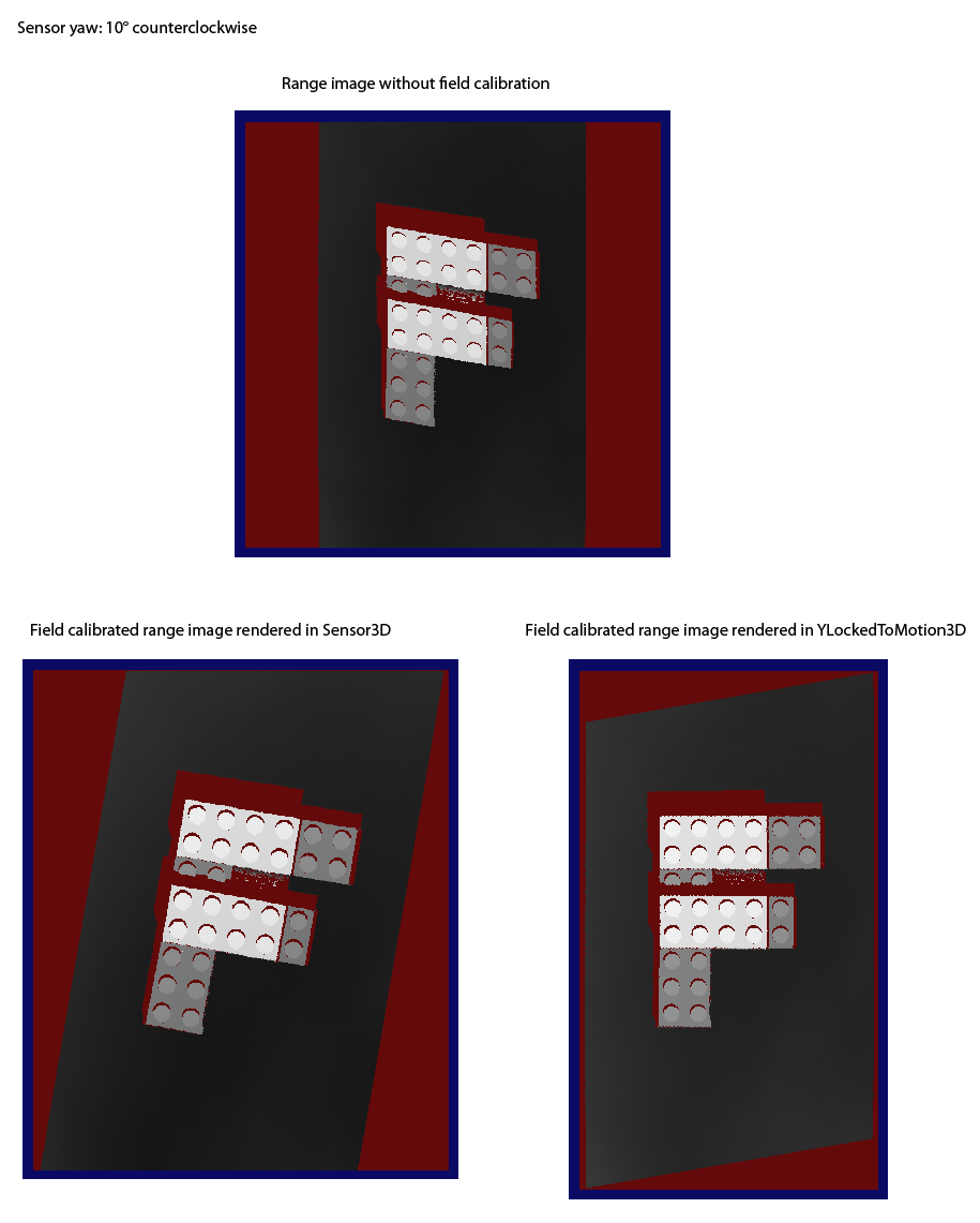
The following image illustrates using field calibration using a single sensor that is yawed with 10° counterclockwise. Skew distortion caused by yawing is removed by field calibration.
Multi-Sensor Acquisition Using Field Calibration
In the multi-sensor case, one range image is acquired from each sensor and the range images are stitched together based on a common physical coordinate space they all share in their coordinate space trees.
- During train time, a calibration target that defines a common physical coordinate space is passed under the sensors. A single field calibration data file is produced during calibrating a multi-sensor system. Also, for each sensor, part of the sensor's field calibration data that is needed to render range data in its YLockedToMotion3D or Sensor3D space is established based on how it sees the calibration target passing under it.
- During run time, you load the field calibration data file into each sensor's AcqFifo (the AcqFifos do not know about each other). For each sensor, the common physical coordinate space (Phys3D) is added to the coordinate space tree of the range image it generates based on the relationship mentioned previously (stored in the field calibration data). A sensor's generated range image is field calibration corrected (deskewed) and rendered in either its YLockedToMotion3D or Sensor3D space. Then, the range images from all sensors are stitched together by the stitching tool based on the common physical coordinate space present in their coordinate space trees, and the stitched range image gets rendered in the coordinate space you specify. The rendering of the stitched range image is performed in either the YLockedToMotion3D or Sensor3D space of the sensor you specify (which space also gets added to the coordinate space tree of each sensor's range image during image acquisition).
The following coordinate spaces are supported to perform range image rendering in.
Sensor3D
The Sensor3D space is a physical right-handed orthonormal coordinate space that is attached to the sensor, whose
- Z axis is in the laser plane, it is parallel to the optical centerline of the sensor, pointing upwards
- X axis is in the laser plane, it is perpendicular to the Z axis, pointing to the left looking at the sensor's mounting pins
- Y axis is perpendicular to the X and Z axes, following the right-hand rule: pointing towards us looking at the sensor's mounting pins
Origin:
Z Origin is at a fixed distance measured in the Z direction from the center of the master pin (which may differ by model)
X Origin is the optical centerline of the displacement sensor
Y Origin is the plane of the laser (at the start of the acquisition)
- Units are in mm
Pixels rendered in this space act like a normal camera: if you tilt the camera, the objects in the rendered image appear tilted. The Sensor3D space is detailed in the Range Image Coordinate Spaces and Associated Parameters topic in the case when the sensor mounting orientation is ideal.
The definition of Sensor3D completely ignores the pose of the frustum.
Rendering range images in Sensor3D is recommended in the following use cases:
- When your sensor(s) can be mounted accurately to match the ideal sensor orientation. In the single sensor case, the objective of field calibration is to correct the Y scale of the image. In the multi-sensor case, the objective of field calibration is to enable range image stitching and to correct the Y scale of the range image. (Range image stitching is performed by the image stitching tool.)
- When sensor mounting is not ideal, nevertheless, it is OK for the application to render range images in Sensor3D.
Extra missing pixels are generated on the sides (image X direction) and not on the front and back (image Y direction).
Advantages: All acquired range data is retained after using field calibration to render the field calibrated range image.
Disadvantages: The field calibrated range image can grow very wide (unlimited), great amount of sensor pitch can cause overflow (bad data) or underflow (missing pixels) in the Z direction.
YLockedToMotion3D
The YLockedToMotion3D space is a physical right-handed orthonormal coordinate space whose Y axis is attached to the motion stage/conveyor belt and whose X and Z axes are attached partly to the motion stage/conveyor belt and to the sensor. The YLockedToMotion3D space
- Y axis is parallel to the observed motion vector, it increases in the same general direction as the Sensor3D Y axis
- Z axis is perpendicular to the motion vector and parallel to the plane containing
- the Sensor3D Z axis and
- the motion vector (with its tail attached to the Sensor3D Z axis)
- X axis is perpendicular to both the Y and Z axes, following the right-hand rule; it is also perpendicular to the Sensor3D Z axis
- Origin lies at the origin of Sensor3D space
- Units are in mm
If the sensor is ideally oriented, YLockedToMotion3D coincides with Sensor3D.
The following images show an example of YLockedToMotion3D relative to Sensor3D in which the sensor setup exhibits yaw, pitch, and roll at the same time.
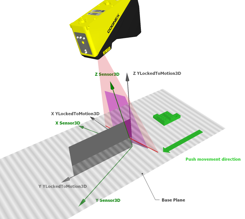
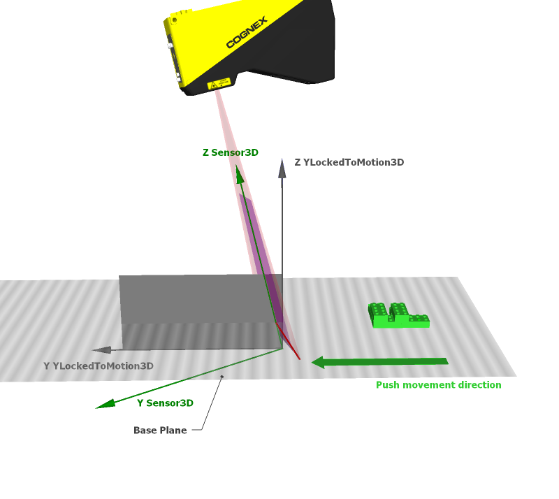
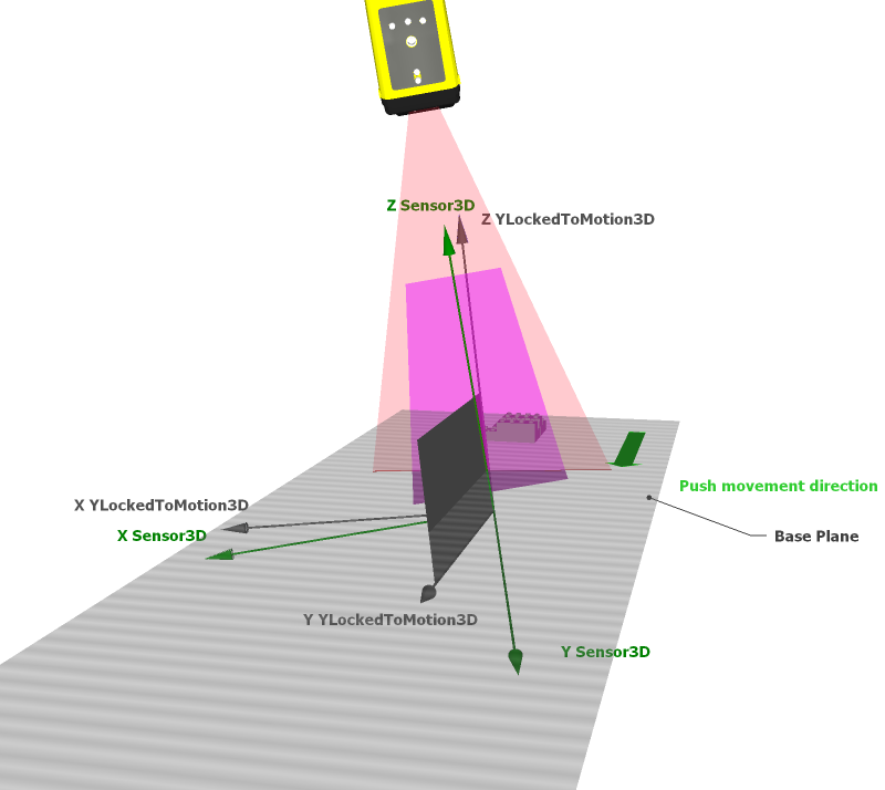
The definition of YLockedToMotion3D completely ignores the pose of the frustum (it primarily cares about the frustum's motion direction).
Depending on the sensor orientation, rendering in YLockedToMotion3D can change the viewing angle of the image relative to Sensor3D (and align it with the motion direction). For example, the viewing angle changes when sensor yaw is present but it does not change when only sensor roll is present (in the latter case YLockedToMotion3D corresponds to Sensor3D).
Rendering range images in YLockedToMotion3D is recommended in the following use cases:
When you cannot guarantee that the Sensor3D Y axis is aligned with the motion direction, and the Y axis of the rendering coordinate space should be aligned with the motion direction (for example, to view range images aligned with the motion direction or to avoid Z overflow or underflow). That is, the objective of field calibration in this case is to compensate for sensor yaw and pitch relative to the ideal sensor orientation, in addition to correcting the Y scale of the range image and (in the multi-sensor case) enabling range image stitching.
Note that because YLockedToMotion3D rolls with the sensor, sensor misalignment consisting of roll is not corrected when rendering in this space. Roll causes the range image content to be tilted around the Sensor3D Y axis. As a result, if you do not wish distortion coming from roll to be present in your corrected range image, you must mount your sensor with high accuracy regarding roll. Note that nonzero yaw + nonzero pitch combinations cause the sensor to roll as well. If you are stitching range images together coming from a long row of displacement sensors (mounted along the X direction) and you are rendering the stitched range image in the YLockedToMotion3D space of the first sensor, then the mounting of the first sensor has to be extremely accurate regarding roll because the nonzero roll angle would cause greater and greater roll distortion as we move toward the other end of the stitched range image. Nevertheless, if you cannot achieve the desired mounting accuracy, you can still compensate for the roll distortion in software by removing the tilt from the base plane of the range image content.
- When you want to inspect an object from the side (left or right) by rolling the sensor, while requiring that your range image be aligned with the motion direction. Because YLockedToMotion3D rolls with the sensor, surfaces the rolled sensor sees on the side will also be visible in the range image rendered in it.
Extra missing pixels are generated on the front and back (image Y direction) and not on the sides (image X direction).
Advantages: Constant image width, no overflow or underflow in the Z direction.
Disadvantages: Rendering in YLockedToMotion3D may discard some of the acquired range data depending on the motion direction relative to the sensor and the features of the object under inspection.
Not Selectable for Rendering: Phys3D
Phys3D is the default name for the common physical coordinate space all range images to be stitched share in their coordinate space trees. Phys3D is available through the API only, it is not exposed in the GUI.
Perform the following steps to set up acquisition with a DS1000 series sensor using field calibration:
I. Perform initial steps:
- Mount, wire, and power on your sensor (described in the Acquiring Images from a DS1000 Series Sensor topic)
- Configure the connection between your computer and the sensor (described in the Acquiring Images from a DS1000 Series Sensor topic)
II. Perform field calibration (described below in this topic)
III. Initialize and configure acquisition using field calibration:
- Initialize acquisition (described in the Acquiring Images from a DS1000 Series Sensor topic)
- Set timing and transport parameters (described in the Acquiring Images from a DS1000 Series Sensor topic)
- Set strobe and trigger parameters (described in the Acquiring Images from a DS1000 Series Sensor topic)
- Configure field calibration (described below in this topic)
IV. Complete the DS1000 acquisition setup using field calibration by using the Displacement Sensor Acquisition Wizard (described below in this topic):
- Set low-level acquisition control parameters on the Camera Setup tab (described in the Acquiring Images from a DS1000 Series Sensor topic)
- Set motion-related parameters on the Motion Setup tab (described below in this topic)
- Set range image properties on the Range Image tab (described below in this topic)
- Set advanced properties on the Advanced tab (described below in this topic)
V. Close the wizard and start acquiring range images (described below in this topic)
VI. Optimize if necessary and finalize acquisition setup (described below in this topic)
Perform the following steps to set up acquisition with a DS1000 series sensor using field calibration:
Mount, wire, and power on your sensor (described in the Acquiring Images from a DS1000 Series Sensor topic).
Configure the connection between your computer and the sensor (described in the Acquiring Images from a DS1000 Series Sensor topic).
To train your system for acquisition using field calibration, perform field calibration using the DS Field Calibrator application as described in the 3D Sensor Field Calibration guide (a separate CHM file supplied with your VisionPro installation, available at %VPRO_Root%\Doc\en\Cognex.DisplacementSensorFieldCalibrator.chm or through the Help menu item of the DS Field Calibrator application). The DS Field Calibrator application is available at Start->All Programs->Cognex->VisionPro->Utilities->DS Field Calibrator.
During successful field calibration using the DS Field Calibrator application, a *.car field calibration data file is generated as the result, which you will supply to an AcqFifo in VisionPro to produce corrected run-time range images that can be stitched together.
Acquisition from a Job can use an Image Source window or CogAcqFifoTools. Setting up acquisition using an Image Source window and a CogAcqFifoTool are similar, therefore, acquisition setup is explained using the Image Source only. Note that if you are using multiple displacement sensors to acquire and stitch range images, you must configure and use multiple CogAcqFifoTools from within the same Job to acquire the range images to be stitched.
Initialize acquisition (described in the Acquiring Images from a DS1000 Series Sensor topic)
Set timing and transport parameters (described in the Acquiring Images from a DS1000 Series Sensor topic)
Set strobe and trigger parameters (described in the Acquiring Images from a DS1000 Series Sensor topic)
Enable and configure field calibration to be used during acquisition on the Calibration tab of the Image Source window. Check the Enable Field Calibration checkbox to enable field calibration, provide the *.car field calibration data file to be used to acquire corrected range images during run time, and set further field calibration parameters. The Calibration tab indicates whether the file you have supplied was successfully opened and read.
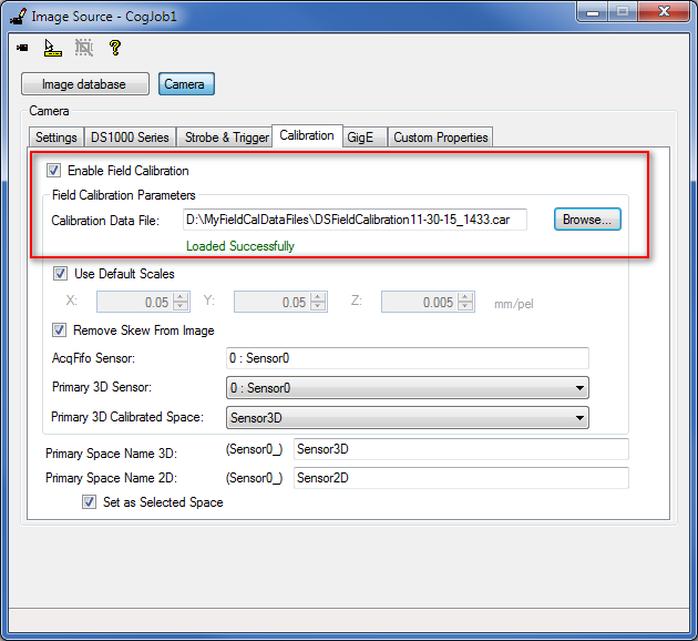
The following sections summarize the field calibration parameters.
Field Calibration Data FileThe *.car FieldCalibrationFile contains the field calibration data to be used to acquire corrected range images during run time. Acquisition will fail if field calibration is enabled and either the file cannot be read or the sensor is not found in the field calibration data file.
X, Y, and Z Scale SettingsThe FieldCalibrationXScale, FieldCalibrationYScale, and FieldCalibrationZScale parameters specify the X, Y, and Z Scale for the range image to be acquired during run time using field calibration. VisionPro offers default scale values for the sensor. If you loaded a field calibration data file, the X, Y, and Z Scale settings from the file are read and loaded into FieldCalibrationXScale, FieldCalibrationYScale, and FieldCalibrationZScale. If you choose to use custom scale settings by unchecking the Use Default Scales checkbox and providing your scale values, these edited scale values are stored in the AcqFifo used during range image acquisition. (If you check the Use Default Scales checkbox again, the custom scale values you entered are lost.)
Remove Skew From Image - Enables Field Calibration to Correct Range ImagesTo render range images corrected (for skew and Y Scale), make sure the Remove Skew From Image checkbox is checked (it is checked by default). This is the RemoveSkewFromRangeImage property in the API.
-
When Remove Skew From Image is set to true, the number of rows may be different between the field-calibrated range image and the non-field-calibrated range image. In this case, the Steps per Line parameter still controls acquisition, regardless of the scaling and the Distance per Cycle parameter. Nevertheless, Steps per Line influences acquisition differently from the non-field-calibrated case as it no longer affects the Y Scale of the range image:
- With a larger Steps per Line setting, the acquired rows will be further apart which may cause image artifacts due to more interpolation between data points. However, this allows a faster motion speed.
- With a smaller Steps per Line setting, more data is acquired and image quality is improved, at the expense of limiting the motion speed (before encoder overruns occur).
- In summary, Steps per Line controls the trade-off between image quality and speed.
- When Remove Skew From Image is set to false, then the number of rows in the field-calibrated range image and the number of rows in the non-field-calibrated range image are the same. In this latter case, Y Scale is thus determined by the Distance per Cycle, Encoder Resolution, and Steps per Line settings.
Primary 3D Calibrated Space specifies the space in which the pixels in the field calibrated range image should be rendered. The available options include Sensor3D and YLockedToMotion3D.
In a multi-sensor setting with image stitching, Primary 3D Sensor specifies the sensor whose Primary 3D Calibrated Space should be used for range image rendering. The drop-down list contains the sensor IDs and sensor names. The sensor ID is a unique index in a multi-camera setup that identifies the sensor. During field calibration training, you can arrange the sensors in the desired order by moving the sensors up or down in the grid. The sensor’s ID is the row index of the sensor within the grid. The system provides a default name for each configured sensor.
If field calibration is enabled, the Primary Space Name 3D corresponds to the field calibrated Primary 3D Calibrated Space. YLockedToMotion3D, Sensor3D, Phys3D, and the Primary 3D Calibrated Space of the Primary 3D Sensor will be added to the 3D coordinate space tree of the acquired range image. Primary Space Name 3D is set as the selected 3D space name in the tree. If Remove Skew From Image is set to true, the acquired range image is rendered in the selected 3D space name (using field calibration correction), that is, in the Primary Space Name 3D. You can give a custom value to the Primary Space Name 3D.
The space defined by Primary Space Name 2D is a 2D space that corresponds to the Z=0 plane in the space defined by Primary Space Name 3D (which corresponds to the Primary 3D Calibrated Space if field calibration is enabled). Primary Space Name 2D will be added to the 2D coordinate space tree of the acquired range image. This space can be used with 2D vision tools to obtain calibrated real-world measurements. The default name for this space is Sensor2D and it is set as the selected 2D space for acquired images. You can also give a different name for the Sensor2D space on this tab, and you can prevent the space from being the selected 2D space by unchecking the Set as Selected Space checkbox. For more information on the Sensor2D Space, see the Using 2D Vision Tools with Range Images topic.
AcqFifo SensorThe ID and Name of the sensor associated with the AcqFifo. These are read from the field calibration data file if the sensor is found. If the sensor is not found, the text box will be empty.
Impact of Field Calibration on the Displacement Sensor Acquisition Wizard
If you enable field calibration, some of the Displacement Sensor Acquisition Wizard GUI (which you will use later to complete acquisition setup) changes compared to not using field calibration. The items affected by field calibration are summarized as follows:
- Some motion-related parameters are locked to the selection made at field calibration training time. In this case, the GUI disables setting these parameters but allows you to view the settings in read-only mode. These parameters are as follows:
- MotionInput
- The number of channels used by the encoder: Single Channel Encoder checkbox on the GUI (UseSingleChannel parameter in the API)
- Encoder Direction (ProfileCameraPositiveEncoderDirection parameter in the API)
- DistancePerCycle - The approximate Distance per Cycle parameter is indicated as measured during field calibration training time. During run-time image acquisition, the exact Distance per Cycle parameter is used, and not the approximate value indicated in the wizard. Because the displayed value is just an approximate value, you should not use this value in any of your calculations.
- AutoCorrectPixelRowOrder is set to true and becomes read only when field calibration is enabled.
X, Y, and Z scales and offsets are not settable when field calibration is enabled.
X, Y, and Z scales are specified for run time image acquisition on the Calibration tab.
Offsets (which the overlay graphics on the Range Image tab of the wizard influence) used to determine range image properties in the X-Z plane, such as range image width, are selected automatically by the system during field calibrated range image acquisition to ensure your range images contain all necessary information and have the proper unified look.
- The range image overlay graphics on the Range Image tab (including the center line, the margins, and the first and last pixel indicators) are not visible when field calibration is enabled.
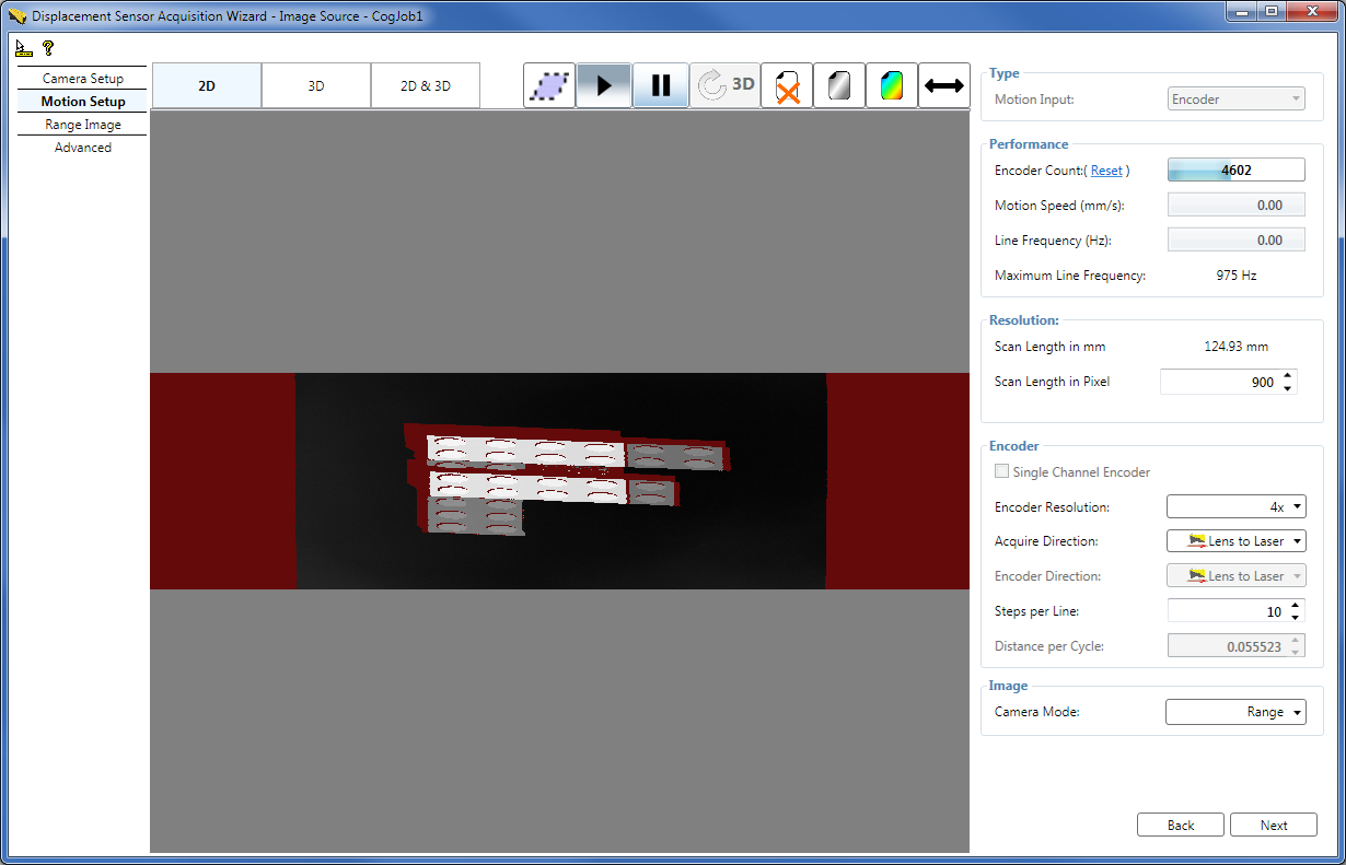
- The waterfall image is acquired and displayed without field calibration by default.
- The deskew button (//) becomes enabled if field calibration is enabled, which corrects the waterfall image based on the field calibration data. If you click the deskew button, waterfall image acquisition will stop. To restart waterfall image acquisition, click the Play button. Note that if you have acquired a RangeWithGrey waterfall image, clicking deskew will result in a deskewed range image (and not a deskewed RangeWithGrey image).
- The 3D display shows the range or RangeWithGrey image corrected based on the field calibration data (even without clicking the deskew button).
Enabling field calibration has no impact on the Camera Setup tab.
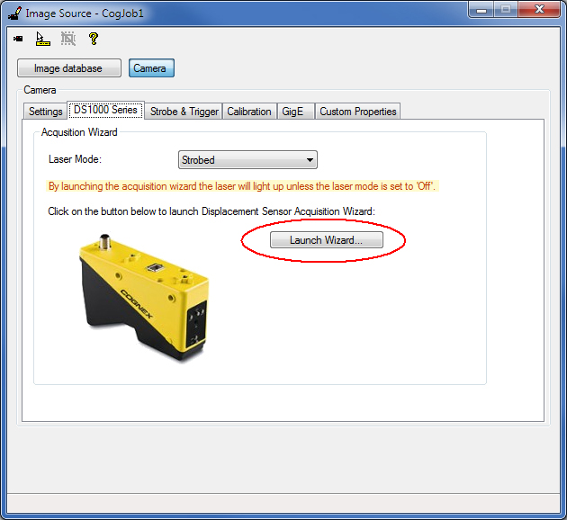
Click the Launch Wizard... button on the DS1000 Series tab to launch the Displacement Sensor Acquisition Wizard.
Note: By launching the acquisition wizard, the laser will light up unless the LaserMode is set to Off.
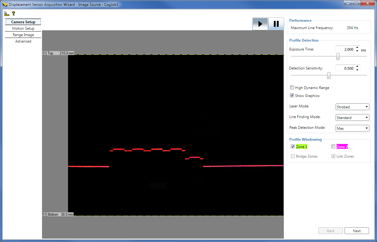
Set low-level acquisition control parameters on the Camera Setup tab (described in the Acquiring Images from a DS1000 Series Sensor topic).
On the Motion Setup tab, set parameters related to the motion underneath the sensor and the output image type. Such parameters include some encoder settings and the Camera Mode setting.
Set the following parameters on the Motion Setup tab:
- Scan Length in Pixel
- EncoderResolution
- Acquire Direction
- Steps per Line
- CameraMode
Because field calibration is enabled, the XScale and YScale parameters are set elsewhere (on the Calibration tab of the Image Source window) and some encoder-related settings including the Encoder Direction and DistancePerCycle parameters are determined automatically by field calibration and displayed as read only in the wizard. (The approximate DistancePerCycle value calculated by field calibration is displayed in the wizard.)
For the detailed description of the parameters on the Motion Setup tab, see the 7. Set Motion-related Parameters on the Motion Setup Tab section (in the Acquiring Images from a DS1000 Series Sensor topic).
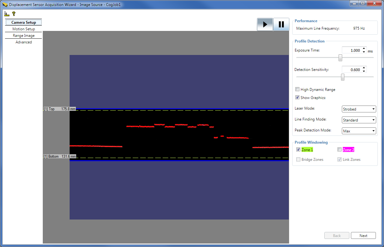
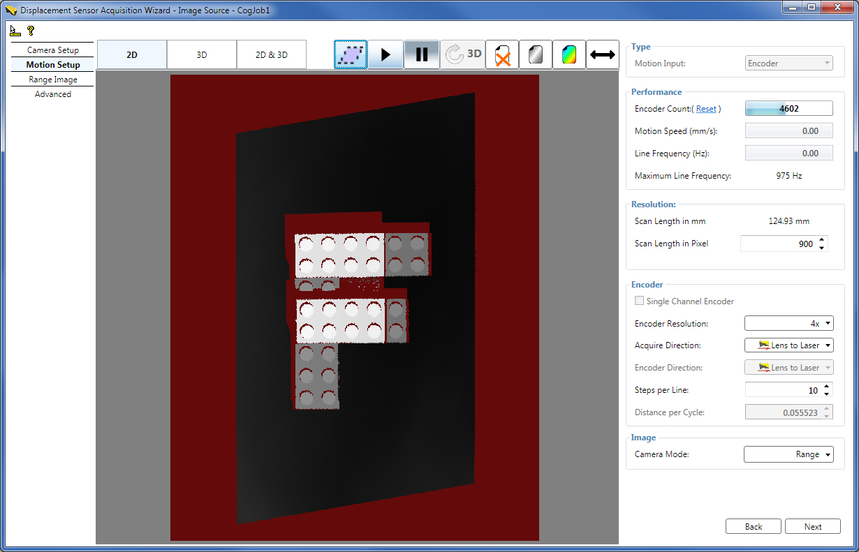
To apply correction to the acquired waterfall image based on the field calibration data, click the deskew button (//) (which is only active if field calibration has been enabled because field calibration results are used to remove skew distortion, stored in the calibration data file). If you click the deskew button, waterfall image acquisition will stop. To restart waterfall image acquisition, click the Play button (>). Note that if you have acquired a RangeWithGrey waterfall image, clicking deskew will result in a deskewed range image (and not a deskewed RangeWithGrey image). The following waterfall image has been rendered deskewed in the YLockedToMotion3D coordinate space:
Set range image properties, which control the characteristics of the generated range image, on the Range Image tab. Such parameters include the Z detection parameters for each detection zone.
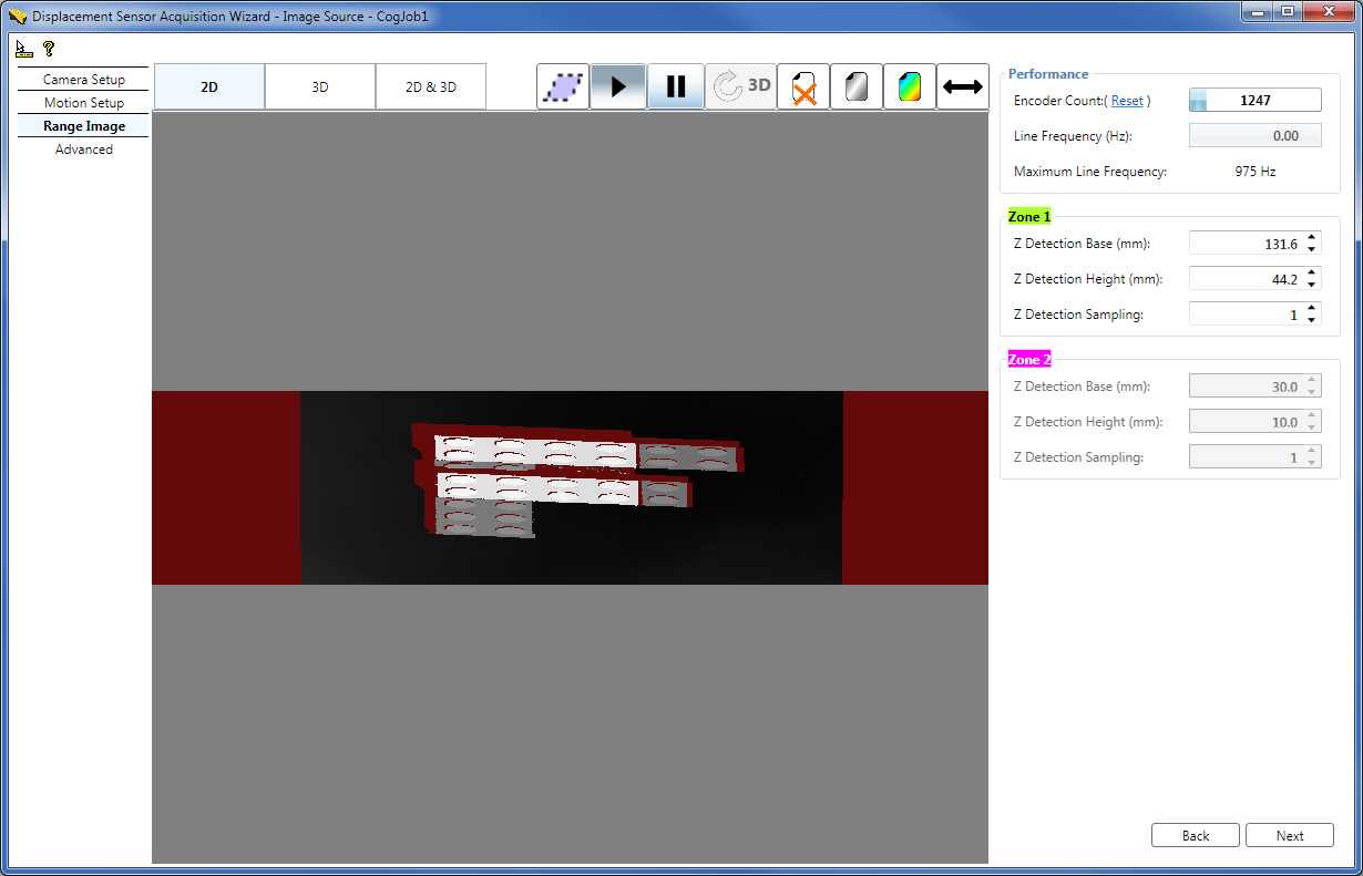
Set the following parameters on the Range Image tab:
- ZDetectionBase for Zone 1 and ZDetectionBase2 for Zone 2 (if Zone 2 is enabled)
- ZDetectionHeight for Zone 1 and ZDetectionHeight2 for Zone 2 (if Zone 2 is enabled)
- ZDetectionSampling for Zone 1 and ZDetectionSampling2 for Zone 2 (if Zone 2 is enabled)
Because field calibration is enabled, the ZScale parameter is set elsewhere (on the Calibration tab of the Image Source window). Offset parameters (which the overlay graphics on the Range Image tab of the wizard influence) used to determine range image properties in the X-Z plane, such as range image width, are selected automatically by the system during field calibrated range image acquisition to ensure your range images contain all necessary information and have the proper unified look. The range image overlay graphics on the Range Image tab (including the center line, the margins, and the first and last pixel indicators) are not visible when field calibration is enabled.
For the detailed description of the parameters on the Range Image tab, see the 8. Set Range Image Properties on the Range Image Tab section (in the Acquiring Images from a DS1000 Series Sensor topic).
You can apply correction to the acquired waterfall image based on the field calibration data by clicking the deskew button (//) on the Range Image tab as well.
Set advanced acquisition parameters on the Advanced tab. Typically, you do not need to change the parameters on this tab for most acquisition scenarios.
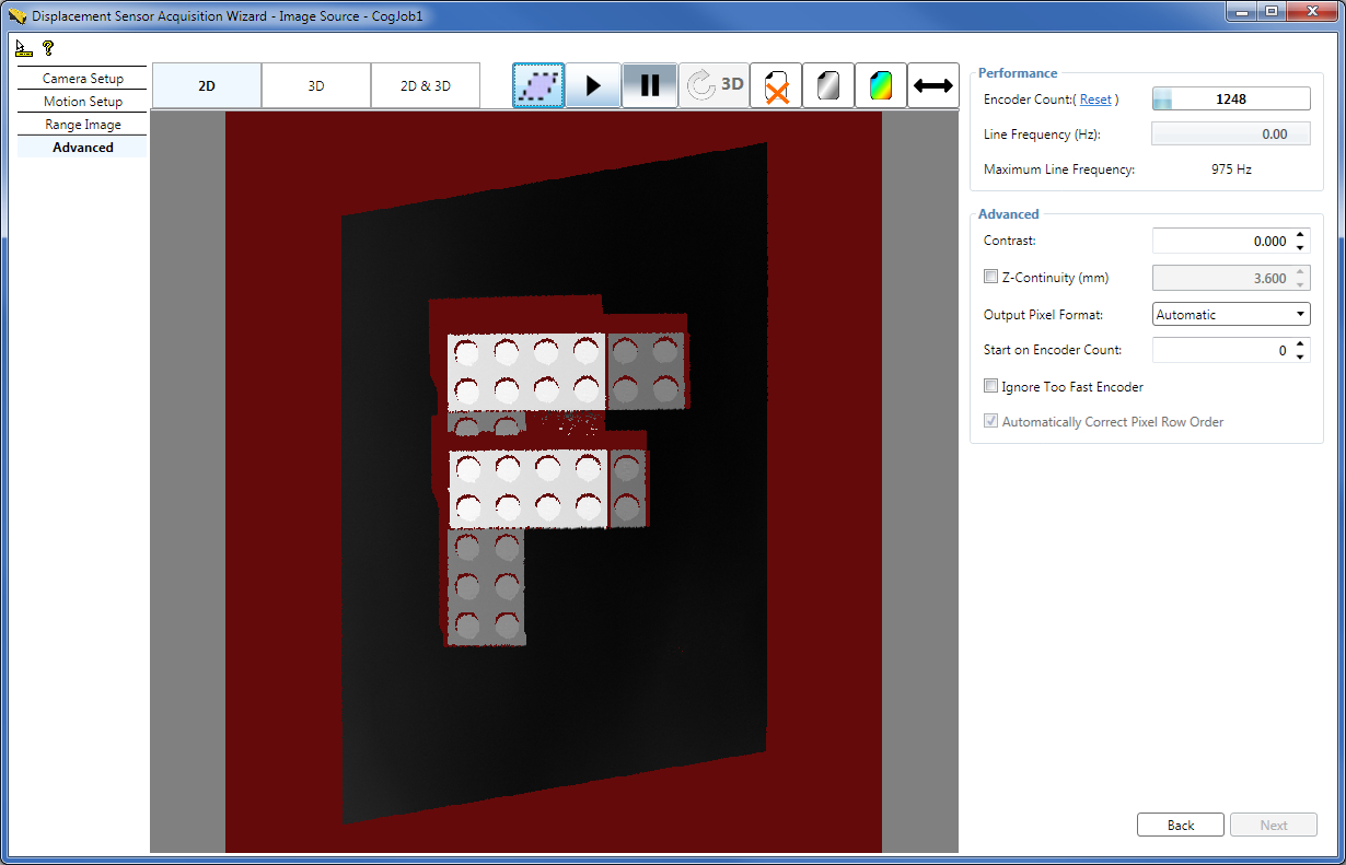
Set the following parameters on the Advanced tab:
Because field calibration is enabled, AutoCorrectPixelRowOrder is set to true and is read only.
For the detailed description of the parameters on the Advanced tab, see the 9. Set Advanced Parameters on the Advanced Tab section (in the Acquiring Images from a DS1000 Series Sensor topic).
You can apply correction to the acquired waterfall image based on the field calibration data by clicking the deskew button (//) on the Advanced tab as well.
If you are using QuickBuild, close the wizard and start acquiring range images from the Job. If you want to acquire range images manually, for example, press the Run button for the Job to acquire an initial range image. You can acquire range images from the sensor from the Job as you would acquire from any other camera.
If you want to use different acquisition settings, stop the acquisition and open the Image Source window and apply new settings there or launch the wizard and set the new acquisition parameters there. Once done, close the wizard and start acquiring again.
Note that simultaneous acquisition from the Job and the wizard is not supported.
If necessary, you can further optimize your acquisition setup by:
- Setting low-level acquisition parameters to enhance the range image quality, for example, to avoid spurious reflections or over-exposure.
- Optimizing for speed and/or resolution along the X, Y, and Z axes.
To optimize acquisition setup, stop acquisition from the Job and reopen and use the Image Source window and the Displacement Sensor Acquisition Wizard. For optimization details, see the Acquisition Parameter Optimization section (in the Acquiring Images from a DS1000 Series Sensor topic) while considering the field calibration specialties detailed in this topic. Once done, to finalize your acquisition setup, close the wizard again and restart acquiring from the Job.
If you are using multiple displacement sensors to acquire and stitch range images, you must configure and use multiple CogAcqFifoTools from within the same Job to acquire the range images to be stitched. You must configure one CogAcqFifoTool for each sensor which will perform acquisition from the sensor. See the Multi-Camera Acquisition in a Single Job topic for information on how to configure a Job to use multiple CogAcqFifoTool instances. Configuring a CogAcqFifoTool is similar to configuring the Image Source window (which is not used in multi-sensor acquisition). Once you have added the CogAcqFifoTools to your Job, configure each as described in the Acquisition Setup Steps with Field Calibration for One Sensor section in this topic.
Not only image acquisition (as described in this topic), but also the image stitching tool can render field-calibration-corrected range images for stitching.
In the case where image acquisition performs field calibration correction, the Remove Skew From Image checkbox must be checked for all CogAcqFifoTools, and it is recommended that all CogAcqFifoTools:
- Use the same scales
- Use the same Primary 3D Sensor
- Use the same Primary 3D Calibrated Space
If you do not want to stitch the range images nor field-calibration-correct (deskew) them, but you want to have the coordinate spaces (YLockedToMotion3D, Phys3D, Sensor3D, and the Primary 3D Calibrated Space of the Primary 3D Sensor, coming from the field calibration data file) in the coordinate space trees of the range images only, then: enable field calibration, choose a field calibration data file, and set Remove Skew From Image to false.