This topic contains the following sections.
- Acquisition Setup Steps
- Acquisition Parameter Optimization
- Optimize for Speed
- Optimize for Resolution along the Z Axis
- Optimize for Resolution along the Y Axis
- Optimize for Resolution along the X Axis
- Setting the Acquisition Parameters based on Concrete Resolution Requirements while Preserving Aspect Ratio
- Camera Feature Support for DS1000 Series Sensors
- Loading An Existing Application
This chapter contains the steps in detail to acquire range images (describing the height profile of 3D objects) using a DS1000 series sensor. Once you set up your sensor including the steps described hereinafter, you can start acquiring images from it like from any generic camera. For information on setting up acquisition with your DS1000 series sensor quickly, see the Getting Started with the the DS1000 topic. Also, see the DS1000 Quick Reference Guide.
Each range image row (or line) is generated based on an acquired intensity image. For the theory of range images, see the Working with 3D Range Images topic. For advanced range image acquisition details including range image coordinate systems, see the Range Image Coordinate Spaces and Associated Parameters topic.
You can achieve a certain performance result (such as acquisition speed or a given resolution) by setting the acquisition parameters for the DS1000 series sensor. During the acquisition setup, you will have to set the following parameter types:
Low-level acquisition control parameters, controlling the CMOS image sensor properties of the GigE camera in the DS1000 series sensor.
These parameters include exposure, contrast, Z detection base and height, Z detection sampling, and detection sensitivity settings.
Motion-related parameters, set to keep track of the motion of the object passing through the Working Section of the sensor.
These parameters include encoder and motion direction settings.
Range image properties, controlling the characteristics of the generated range image.
These parameters include origin, scale, and image width and height settings.
Strobe and trigger settings, controlling the behavior of the laser and triggering.
These parameters include the laser mode and the trigger mode.
Timing and transport parameters.
These parameters include overall acquisition timeout, transport timeout, transported packet size, and latency level.
Once you set up your sensor, you can close the Displacement Sensor Acquisition Wizard and the Image Source window and you can start acquiring from the Job as you would from any other generic camera.
The initial range image acquisition steps, the parameter optimization to achieve a certain performance result, and the camera feature support summary for DS1000 series sensors are described hereinafter.
Perform the following steps to set up acquisition with a DS1000 series sensor:
- Mount, wire, and power on your sensor
- Configure the connection between your computer and the sensor
- Initialize acquisition
- Set timing and transport parameters
- Set strobe and trigger parameters
Complete the acquisition setup using the Displacement Sensor Acquisition Wizard:
- Set low-level acquisition control parameters on the Camera Setup tab
- Set motion-related parameters on the Motion Setup tab
- Set range image properties on the Range Image tab
- Set advanced parameters on the Advanced tab (typically not required for most scenarios)
- Set the coordinate spaces (optional)
- Close the wizard and start acquiring range images
Mount, wire, and power on your sensor as described in the DS1000 Quick Reference Guide. For sensor setup using field calibration, also see the DS Field Calibration Hardware Trigger Setup guide.
The DS1000 series sensor has a GigE camera, which observes objects passing through the Working Section. Once you connected and applied power to your sensor, configure your sensor in your network as a general GigE camera using the GigE Vision Configuration Tool utility. Choose All Programs->Cognex->VisionPro->Utilities->GigE Vision Configuration Tool from the Start menu to start the tool. Configure the network interface card (NIC) and camera IP addresses. For information on GigE camera configuration, see the GigE Vision Cameras User’s Guide, the GigE topics, and the CogAcqGigEVisionTransport class in this chm file.
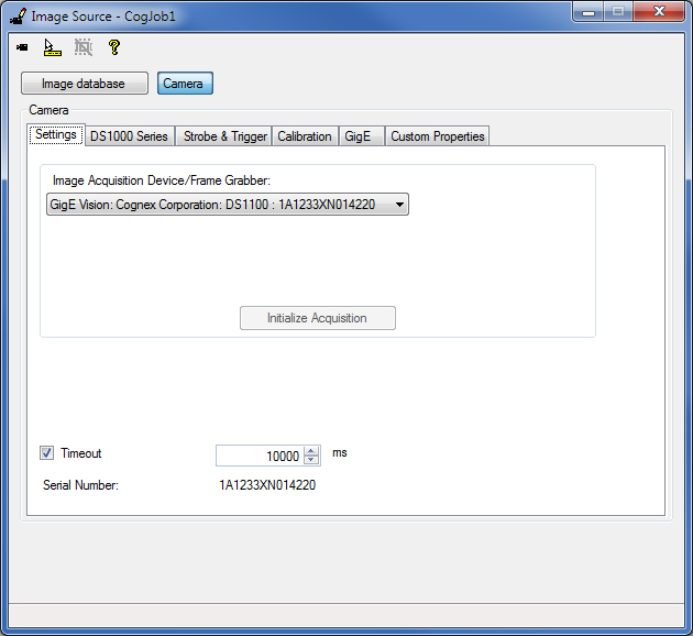
There are 3 ways to initialize the DS1000 series sensor: in QuickBuild's Image Source, programmatically, or using the CogAcqFifoTool and CogAcqFifoEditV2 control. You can use the CogAcqFifoEditV2 control in your Windows forms application.
If you are using QuickBuild, select your DS1000 series sensor as the Image Source and click Initialize Acquisition on the Settings tab.
From the API, you must specify a special video format when calling CogFrameGrabberGigE.CreateAcqFifo as follows:
Fg.CreateAcqFifo(“Cognex NullFormat“, CogAcqFifoPixelFormatConstants.Format8Grey,0,true)
Hereinafter, further steps are listed for using QuickBuild's Image Source for acquisition setup.
On the Settings tab, you can enable and set an overall acquisition Timeout. When adjusting this timeout value, consider that the time needed to acquire a range image is strongly influenced by the number of range image rows and the time needed to acquire a row. For initial acquisition setup, Cognex recommends that you either disable this timeout or set it to a value that is great enough not to cause timeout.
On the GigE tab, you can specify a TransportTimeout, which determines the maximum time for the camera to transmit an image. For initial acquisition setup, Cognex recommends that you leave this value at the default setting (2000 ms). You can also specify the LatencyLevel of the GigE Vision performance driver. The (default) value of 3 gives low CPU load at the expense of higher latency and less reliability. The value of 0 gives more reliable acquisition with less latency at the expense of higher CPU usage.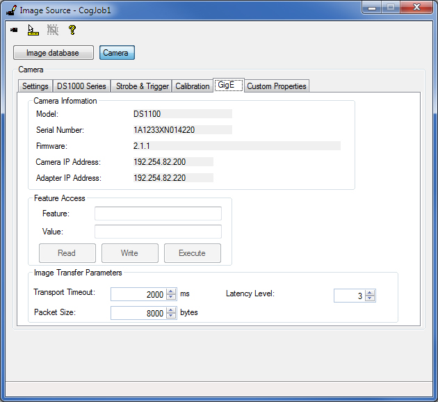
Strobe and trigger settings control the behavior of the laser and triggering. The default settings for these parameters are suitable for initial acquisition setup.
This section contains the following subsections.
Laser Mode
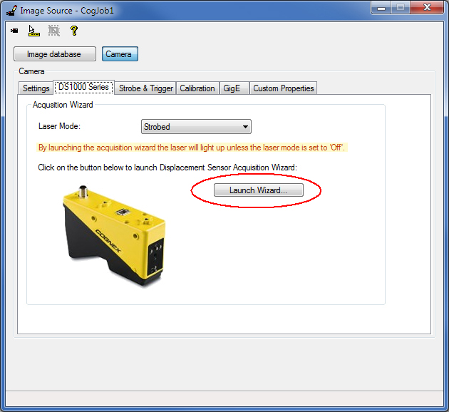
On the DS1000 Series tab, specify the LaserMode of operation:
- Strobed - The laser is on when acquisition is performed
- On - The laser is on continuously. This option is useful when you set up sensor mounting: it allows you to position the sensor so its Working Section is properly aligned without having to acquire actual images.
- Off - The laser is off

Note that you can also change this setting in the Displacement Sensor Acquisition Wizard, used in the following acquisition steps.
Trigger Model and Type
On the Strobe & Trigger tab, you can specify the TriggerModel, which defines the trigger mode for the acquisition (whether you acquire an intensity image, intensity image with graphics, or a range image):
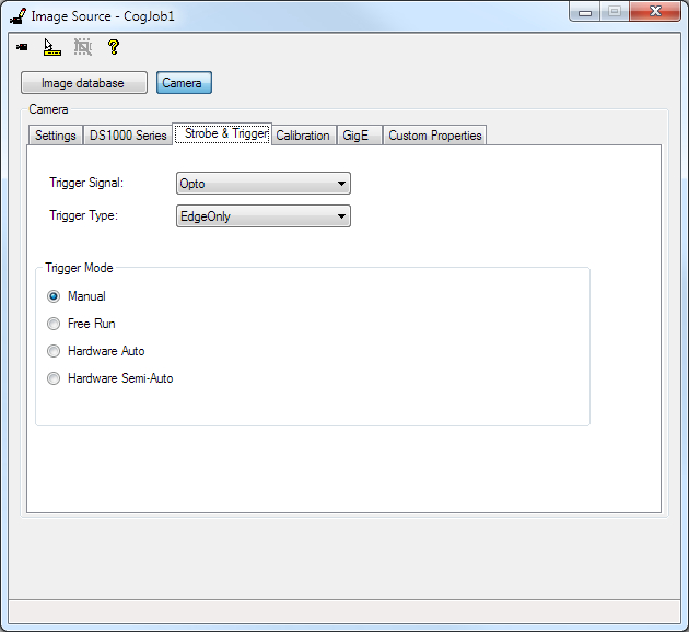
- Manual - The sensor acquires an image when you press Run in QuickBuild or you call StartAcquire from the API, without waiting for an external trigger
Free Run
When set from the API, the sensor continuously acquires images at the Maximum Line Frequency. The Maximum Line Frequency is the inverse of the Line Time, which is the time needed to acquire an intensity image and process it to generate a range image line. The Line Time is described in detail hereinafter. Your application must call CompleteAcquire to get the next available image.
In QuickBuild, only one image is acquired in this mode when you press Run (that is, it is equivalent to the Manual mode). To acquire and process multiple images, you must press the Run Job Continuously button. When TriggerModel is Free Run and the Job is run continuously, there will not be any gaps between images. This allows parts longer than what the camera can acquire in a single acquisition to be imaged by acquiring multiple short images and stitching them together. For example, 10 images of 5000 lines instead of one image of 50000 lines.
Hardware Auto
If the TriggerType is set to EdgeOnly:
When set from the API, the sensor acquires an image after detecting a low->high edge transition on an external trigger line. Your application must call CompleteAcquire to get the next available image.
In QuickBuild, the sensor acquires a single image if Run is pressed and after this a low->high edge transition on an external trigger line is detected. To acquire multiple images, press the Run Job Continuous button, after this the sensor acquires multiple images, one image after each low->high edge transition detection on an external trigger line.
If the TriggerType is set to EdgeAndLevel:
When set from the API, the sensor acquires an image after detecting a low->high edge transition on an external trigger line and acquires further images as long as the external trigger line level stays high. When the external trigger line level has a high->low transition, the sensor completes the acquisition of the current image being acquired and acquires no further images. Your application must call CompleteAcquire to get the next available image after each image acquisition.
In QuickBuild, the sensor acquires a single image if Run is pressed and after this a low->high edge transition is detected on an external trigger line. To acquire multiple images, press the Run Job Continuous button, after this the sensor acquires an image after detecting a low->high edge transition on an external trigger line and acquires further images as long as the external trigger line level stays high. When the external trigger line level has a high->low transition, the sensor completes the acquisition of the current image being acquired and acquires no further images.
Keeping the external trigger line set high (after an initial image acquisition after a low->high edge transition) can be useful for parts that are longer than the maximum single image size or for variable length parts. For parts longer than the maximum single image size, the group of acquired images from a single trigger (reaching from the low->high to the high->low level transition) can be stitched together to form a larger image of the part.
Notes:
- If the acquisition ends by a high->low level transition and there is a low->high edge transition on the external trigger line before the acquisition of the current (last) image completes, no images will be acquired for this low->high edge transition and an isMissed error is generated. If an isMissed error occurred, further multiple image acquisition can only be started by a low->high edge transition (after the acquisition of the current (last) image completed), level high state is not enough. Note that a high->low edge transition in this case triggers only one image to be acquired.
- If you are acquiring multiple images of a long part, do not change any acquisition properties while the trigger line is active. To write the new properties to the camera, acquisition will be interrupted. After changing any acquisition property during active acquisition with trigger level high state, further multiple image acquisition can only be started by a low->high edge transition (after the acquisition of the current (last) image completed), level high state is not enough. Note that a high->low edge transition in this case triggers only one image to be acquired.
- Acquisition errors (such as the IsTooFastEncoder error if the IgnoreTooFastEncoder option was not selected) will stop the acquisition of further images. If you are acquiring multiple images of a long part and you encounter an acquisition error, images that have already been acquired for the part are recommended to be discarded. If an acquisition error occurred, further multiple image acquisition can only be started by a low->high edge transition (after the acquisition interval of the current (last) image has been covered), level high state is not enough. Note that a high->low edge transition in this case triggers only one image to be acquired.
Hardware Semi-Auto
If the TriggerType is set to EdgeOnly:
When set from the API, the sensor acquires an image after detecting a low->high edge transition on an external trigger line if you called StartAcquire prior to the trigger detection. Your application must call CompleteAcquire to get the next available image.
In QuickBuild, the sensor acquires a single image if Run is pressed and after this a low->high edge transition on an external trigger line is detected. To acquire multiple images, press the Run Job Continuous button, after this the sensor acquires multiple images, one image after each low->high edge transition detection on an external trigger line. (In QuickBuild, this is equivalent to the hardware auto mode.)
If the TriggerType is set to EdgeAndLevel:
When set from the API, the sensor acquires an image after detecting a low->high edge transition on an external trigger line if you called StartAcquire prior to the trigger detection. Even if the external trigger line stays high, the sensor will not acquire further images (or unpredictable gaps between images will occur). Your application must call CompleteAcquire to get the next available image.
In QuickBuild, the sensor acquires a single image if Run is pressed and after this a low->high edge transition is detected on an external trigger line. To acquire multiple images, press the Run Job Continuous button and:
- If no multiple acquisitions are pre-queued, after you pressed the Run Job Continuous button the sensor acquires multiple images after each low->high edge transition. Even if the external trigger line stays high, the sensor will not acquire further images (or unpredictable gaps between images will occur).
- If multiple (greater than or equal to 2) acquisitions are pre-queued, after you pressed the Run Job Continuous button the sensor acquires an image after detecting a low->high edge transition on an external trigger line and acquires further images as long as the external trigger line level stays high. When the external trigger line level has a high->low transition, the sensor completes the acquisition of the current image being acquired and acquires no further images.
Notes for the case when multiple (greater than or equal to 2) acquisitions are pre-queued:
- If the acquisition ends by a high->low level transition and there is a low->high edge transition on the external trigger line before the acquisition of the current (last) image completes, no images will be acquired for this low->high edge transition and an isMissed error is generated. If an isMissed error occurred, further multiple image acquisition can only be started by a low->high edge transition (after the acquisition of the current (last) image completed), level high state is not enough. Note that a high->low edge transition in this case triggers only one image to be acquired.
- If you are acquiring multiple images of a long part, do not change any acquisition properties while the trigger line is active. To write the new properties to the camera, acquisition will be interrupted after as many images have been acquired as defined by the pre-queue number. After changing any acquisition property during active acquisition with trigger level high state, further multiple image acquisition can only be started by a low->high edge transition (after the acquisition of the current (last) image completed), level high state is not enough. Note that a high->low edge transition in this case triggers only one image to be acquired.
- Acquisition errors (such as the IsTooFastEncoder error if the IgnoreTooFastEncoder option was not selected) will stop the acquisition of further images. If you are acquiring multiple images of a long part and you encounter an acquisition error, images that have already been acquired for the part are recommended to be discarded. If an acquisition error occurred, further multiple image acquisition can only be started by a low->high edge transition (after the acquisition interval of the current (last) image has been covered), level high state is not enough. Note that a high->low edge transition in this case triggers only one image to be acquired.
Trigger Signal
The TriggerSignal control allows you to choose between Differential and Opto trigger signals. The choice that you make here alters the electrical characteristics of the camera's input trigger line.
The Differential should only be used if you are using the Cognex supplied Power and I/O Cable to directly connect a DS1000 Series camera to the SENSOR1 or SENSOR2 port on a Cognex Vision Controller. For all other configurations, select Opto.
Click the Launch Wizard... button on the DS1000 Series tab to launch the Displacement Sensor Acquisition Wizard.
Note: By launching the acquisition wizard, the laser will light up unless the LaserMode is set to Off.
Low-level acquisition control parameters control the CMOS image sensor properties of the GigE camera in the DS1000 series sensor. The default settings for these parameters are suitable for initial acquisition setup and most acquisition conditions.
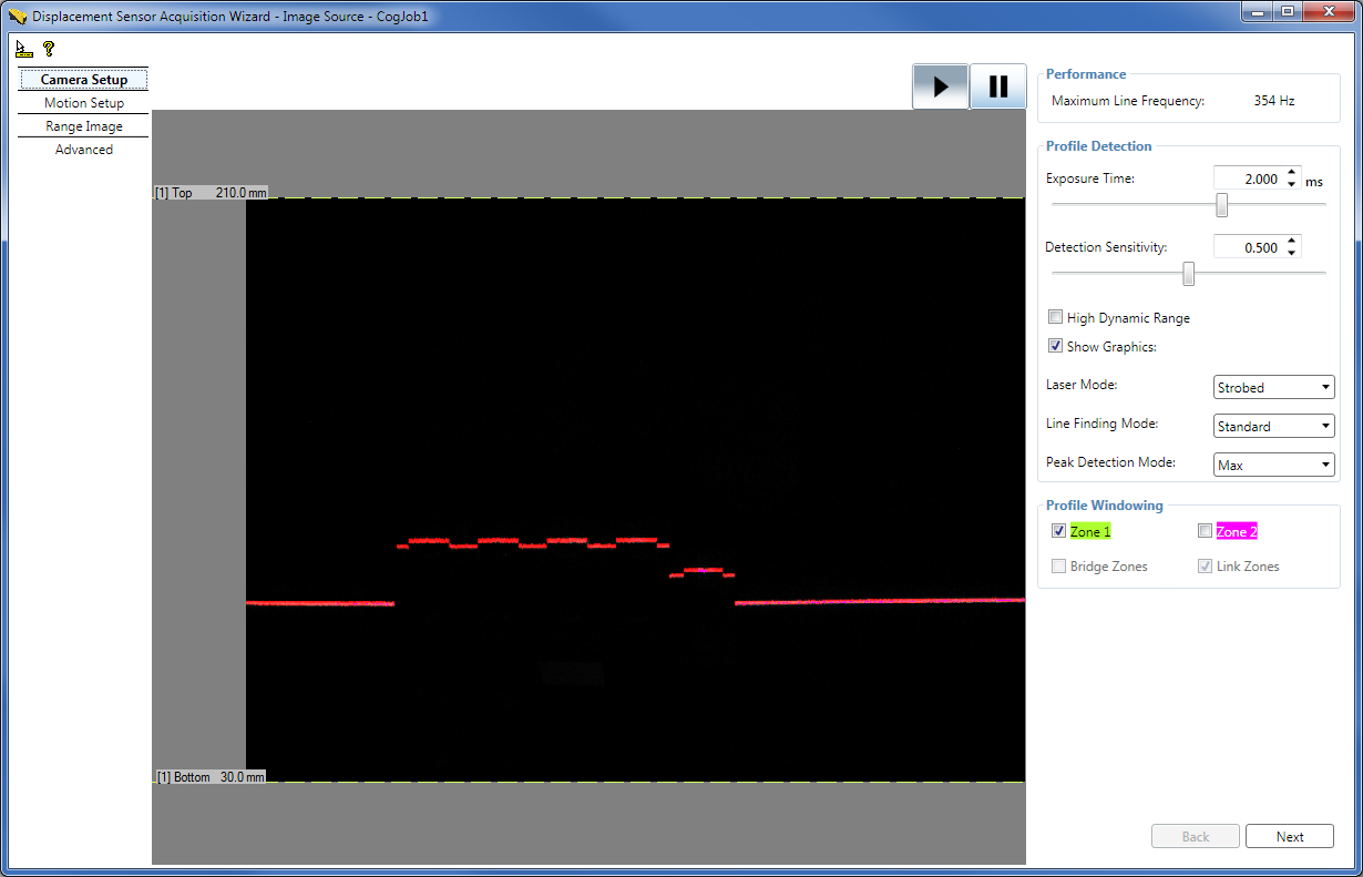
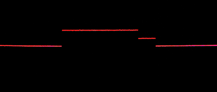
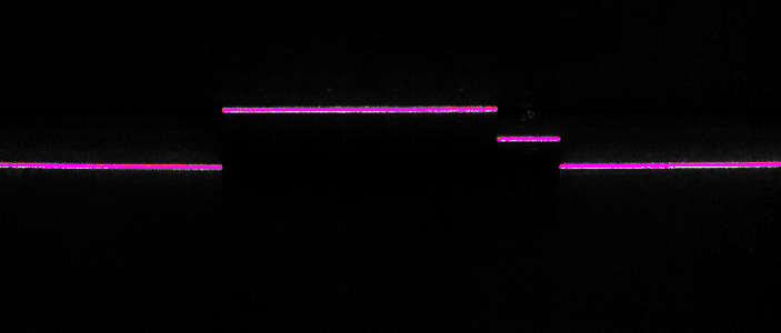
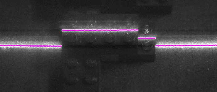
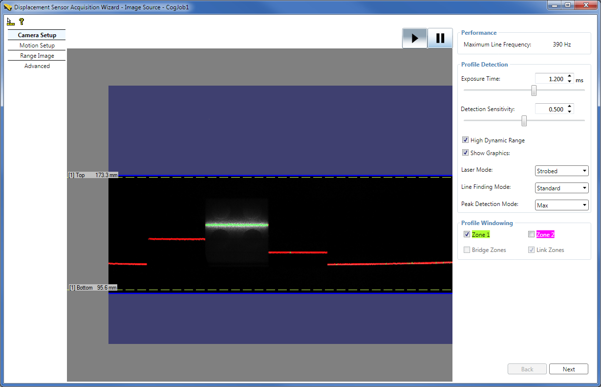
The Camera Setup tab of the wizard continuously displays the intensity image the GigE camera sees, the graphics that displays the line finding results (referred to as the bright stripe curve finding results elsewhere), and contains most low-level acquisition control parameters. It also displays the Maximum Line Frequency for the current settings, directly read from the DS1000 sensor. You can use intensity images or intensity images with graphics to verify that an object you want to inspect appears correctly in the DS1000 series sensor's camera. For example, you may want to verify whether laser is reflected from all object parts that you want to inspect. Other uses include setting correct laser reflection, described hereinafter.Set Profile Detection Parameters: Exposure Time, Laser Detection Sensitivity, High Dynamic Range, Line Finding Mode, Laser Mode, Peak Detection Mode, and Contrast
On the Camera Setup tab, you can set the Exposure time of the camera in ms. Higher values let the camera collect more information about the laser line reflected from the surface of the object under inspection and are therefore used for surfaces that are less reflective (for example, dark).
Recommendations for setting the Exposure time using an acquired intensity image:- Set Exposure time to avoid saturation, if possible.
- Aim to have laser line pixel values in the range 40 through 245.
- Set Exposure time low enough to minimize or avoid spurious reflections, if possible.
Setting high Exposure time may reduce the Maximum Line Frequency.
Set the laser DetectionSensitivity parameter. A higher value makes the laser easier to find and allows a lower exposure setting, which in turn may allow a higher Maximum Line Frequency. A lower value will prevent mistaking noise for the laser in areas where the laser is obscured.
You can enable HighDynamicRange for the camera to use multiple exposures to increase the dynamic range. This is useful when the laser line passed over both dark and highly reflective regions. Enabling HighDynamicRange will reduce the Maximum Line Frequency. See more on HighDynamicRange in subsection Enable High Dynamic Range for Surfaces with Varying Reflectivities.
You can disable displaying the line finding graphics if you want to view the intensity image only on the Camera Setup tab.
You can set the LaserMode of operation on the Camera Setup tab also, as described previously.
You can specify the Line Finding Mode (LaserDetectionMode in the API). Setting it to Fast may increase the Maximum Line Frequency at the cost of accuracy. Standard mode is the default. Note that appropriate Exposure time settings for the Fast mode may differ from that for the Standard mode. Intensity images appear brighter in Fast mode; therefore, you may need to decrease the Exposure time to avoid saturation. Decreasing the Exposure time may result in additional Maximum Line Frequency increase. You can also specify the Binary mode which allows higher line rates than the Fast mode, but with less accuracy. If you specify the Binary mode, you specify the BinarizationThreshold instead of the DetectionSensitivity to specify the threshold pixel value for laser detection. Setting the BinarizationThreshold to 255 will not exclude very bright pixel values, such as pixels that are saturated. Setting a very low BinarizationThreshold, which means a laser hit will be found almost everywhere, will not produce proper line finding. In this mode, you can specify the Binary Peak Width (MinimumBinarizationLineWidth in the API), which specifies how many contiguous 1's (that is, pixel value above BinarizationThreshold) are needed to detect a peak in the image.
You can specify the PeakDetectionMode: Max which uses the peak of the maximum strength for height calculation (default), Closest which uses the peak closest to the camera for height calculation, and Farthest which uses the peak farthest from the camera for height calculation. Selecting Farthest or Closest instead of Max might slightly reduce the Maximum Line Frequency. You can use the Closest or Farthest PeakDetectionMode to reduce possible spurious peaks if you are sure that the closest or farthest peak in the intensity image column is the correct surface to use. This is useful in cases where there is a stronger, but spurious, peak elsewhere. For example, if you were measuring the height of a semi-transparent cover on top of an opaque object, you would get a weak peak from the cover and a stronger peak from the object beneath the cover. But because you want to measure the cover and not the object underneath it, you specify the Closest peak.
On the Advanced tab, you can set the Contrast for the GigE camera also.
Set Profile Windowing Parameters: Top and Bottom for each Detection Zone
On the Camera Setup tab, set profile windowing parameters: enable Zone 1 and/or Zone 2, set top and bottom of each zone, set whether they should be linked, and set whether they should be bridged.
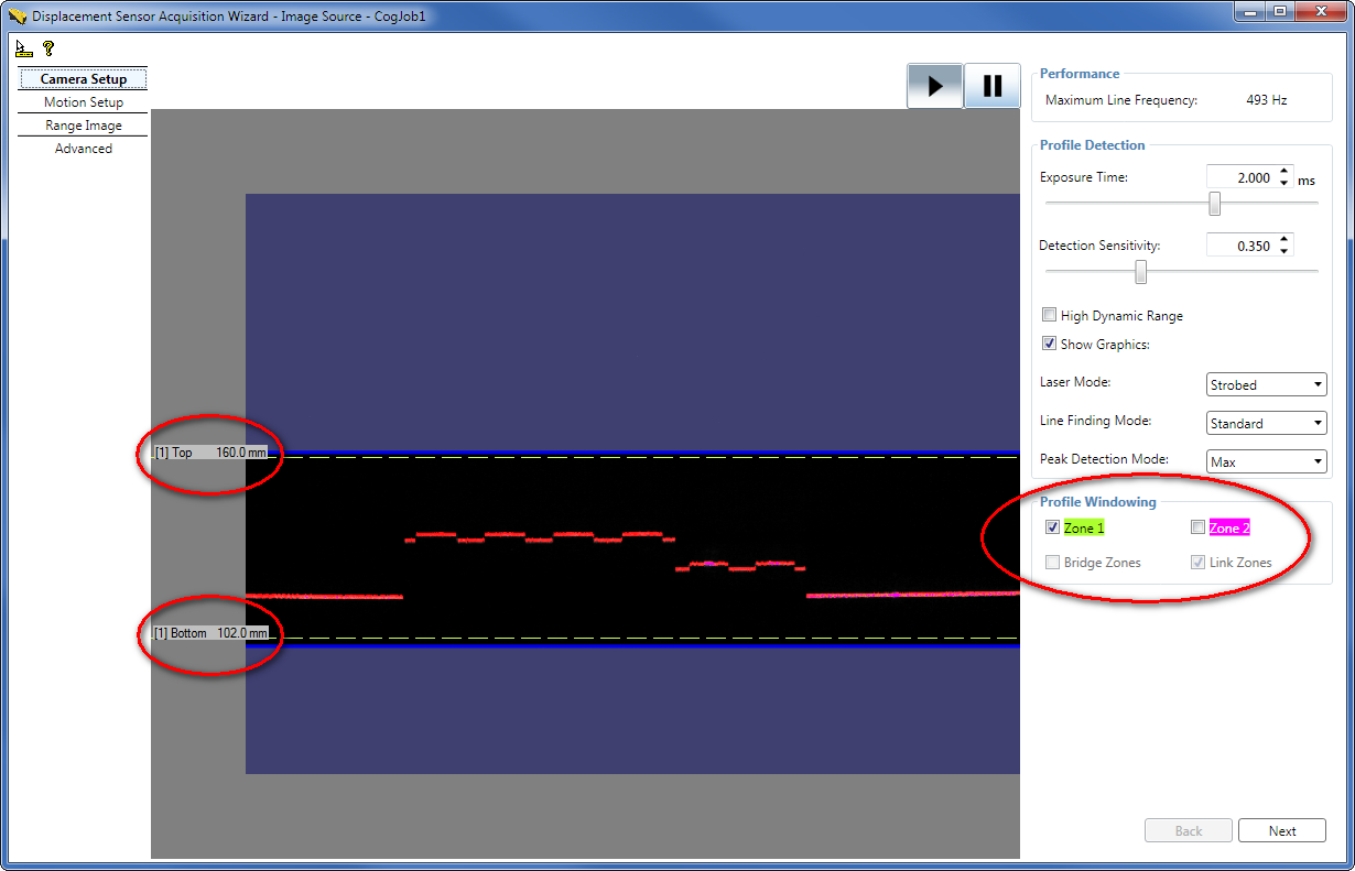
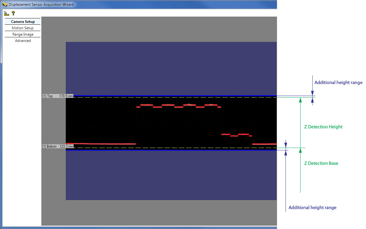
By default, Zone 1 is the height range in which heights will be detected (in mm). Set the top and bottom of Zone 1 by grabbing and moving the dashed lines representing them to define this height range. The top and bottom of the zone define the ZDetectionBase and ZDetectionHeight parameters for the zone. The intersection of this height range and the Working Section defines the Working Section of Interest.
Sometimes the acquired images may include additional heights slightly above or below the height limits of the Working Section of Interest. Therefore, do not use the height limits (top and bottom and the associated ZDetectionBase and ZDetectionHeight parameters) to attempt to filter out height ranges beyond the height limits; rather consider the range defined by these height limits as the range where the acquisition system guarantees line finding to be performed and therefore features with heights in this range to appear in acquired images.Note that the position of the dashed lines is only approximation.
For the exact definitions of these parameters based on the Sensor3D Space of DS1000 series sensors and for how they relate to the Working Section, see the Range Image Coordinate Spaces and Associated Parameters topic.
Note that you can set the ZDetectionBase and ZDetectionHeight parameters directly by entering values in mm (you can define the value up to one decimal place) and z-direction sampling for the zone on the Range Image tab of the wizard.
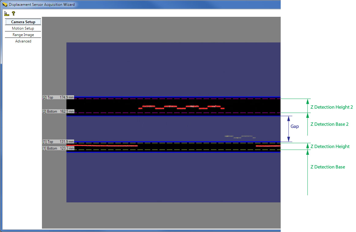
You may define a second height range for the Working Section of Interest, Zone 2, by enabling it and setting the top and bottom of it by grabbing and moving the dashed lines representing them. The top and bottom of Zone 2 define the ZDetectionBase2 and ZDetectionHeight2 parameters. This is useful when you are interested in two height ranges separated by a gap, and you are not interested in the height ranges of the gap. By specifying a gap in the Working Section of Interest, the Maximum Line Frequency may be increased. Heights in the gap are not detected by the sensor.
In addition for Zone 1 and Zone 2, you can set the ZDetectionSampling and ZDetectionSampling2 parameters respectively on the Range Image tab of the wizard to set the sampling interval of processed rows in the intensity image. The default value of 1 processes each row, and 2 processes every other row. Reducing the number of rows processed may speed up acquisition at the cost of accuracy.
If Zone 1 and Zone 2 are enabled, the Working Section of Interest is defined as follows:
If Zone 1 and Zone 2 are not bridged (default) and a gap exists between the two zones (the zones are not touching each other), detection is performed in the zones and detection is not performed in the gap.
In the special case when the two zones are touching each other, generally, Zone 1 and Zone 2 are combined into a single zone starting at the bottom of the lowest zone and ending at the top of the highest zone. Detection is performed in this combined zone using the individual ZDetectionSampling setting for each zone. The one exception is the case when ZDetectionSampling is set to 2 and ZDetectionSampling2 is set to 1; in this case there will be a gap of 4 intensity image rows at the border of the two zones in which no detection will be performed. If you do not want this gap to be present, you can bridge the two zones.
- If Zone 1 and Zone 2 are bridged by enabling the BridgeDetectionZones parameter, Zone 1 and Zone 2 are combined into a single zone starting at the bottom of the lowest zone and ending at the top of the highest zone. The ZDetectionSampling setting from Zone 1 is used for the entire combined zone.
The Maximum Line Frequency achievable by the sensor with the current acquisition settings is calculated and displayed. It is in an inverse relationship with the Line Time, which is the time needed to acquire an intensity image and process it to generate a range image line.
The approximation of the Line Time is the following: Line Time ≈ MAX (Exposure time, Intensity Image Processing Time) That is, the Line Time approximately equals the Exposure time if the Exposure time is greater than the Intensity Image Processing Time; and the Line Time approximately equals the Intensity Image Processing Time if the Intensity Image Processing Time is greater than the Exposure time. The settings that influence the Intensity Image Processing Time include the following:- Z detection zone sizes: ZDetectionBase, ZDetectionHeight, ZDetectionSampling (Zone 1) ZDetectionBase2, ZDetectionHeight2, ZDetectionSampling2 (Zone 2)
- Whether there should be a gap between the two detection zones: BridgeDetectionZones
- Line Finding Mode (LaserDetectionMode in the API)
Maximum Line Frequency = 1 / Line Time
From the API, read the MaximumLineFrequency value. Any errors reading the MaximumLineFrequency from the camera are handled (and 0 is returned in an error case); also a changed event is fired whenever any change is made that might affect the Maximum Line Frequency, which avoids the need to poll the feature in the GUI. For example, if another acquisition FIFO (or job) is using the camera when a setting is changed, the new acquisition code will not be able to write the new settings to the camera; in this case, MaximumLineFrequency will return 0.
Once done, click Next in the Displacement Sensor Acquisition Wizard to get to the Motion Setup tab or click the Motion Setup tab text on the left.
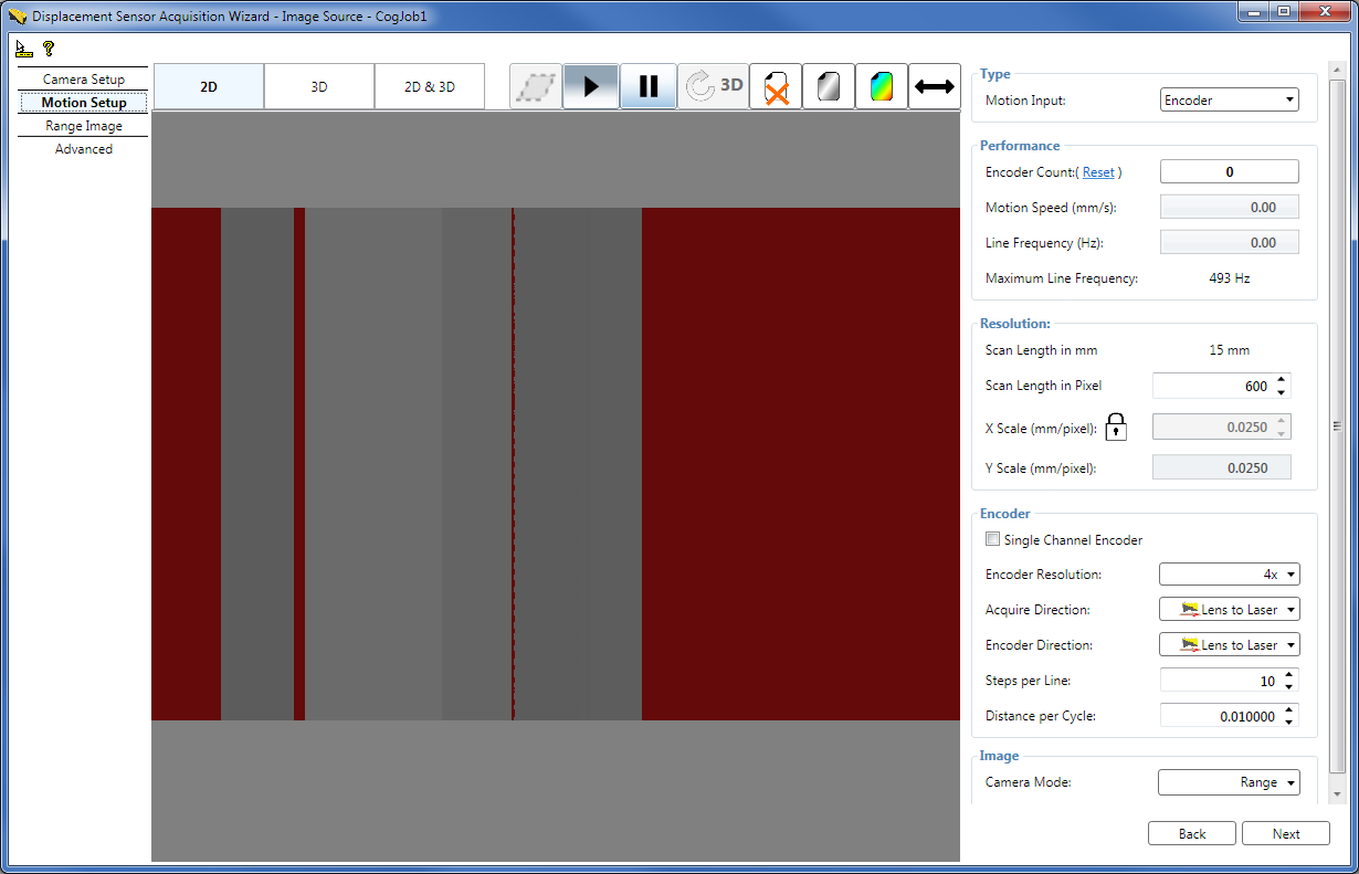
On the Motion Setup tab, set parameters related to the motion underneath the sensor and the output image type. Such parameters include encoder settings and X and Y scale settings.
Encoders
Encoders are used to track motion, for example, of a conveyor belt. The encoder is attached to the conveyor belt and provides a specific set of signals when the conveyor belt travelled a certain distance (Step). An intensity image acquisition for the range image generation is initiated by the encoder signal of a Step. Single channel encoders have a single signal channel and are therefore only able to detect the presence of motion but not the direction of the motion. Dual channel encoders have quadrature signal channels, which enable them to detect the direction of the motion as well. The following image illustrates the two signal channels (Phase A and Phase B) of a dual channel encoder.
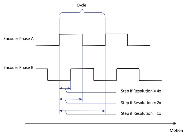
If the EncoderResolution is set to 4x, the encoder produces Steps for range image acquisition four times as frequent as it completes Cycles, each Step being quarter as long as the DistancePerCycle.
When 4x is used, each Step corresponds to the distance between individual edges of the quadrature waveform.
If the EncoderResolution is set to 2x, the encoder produces Steps for range image acquisition twice as frequent as it completes Cycles, each Step being half as long as the DistancePerCycle.
When 2x is used, encoder Steps are produced based on the edges of Phase A.
If the EncoderResolution is set to 1x, the encoder produces Steps for range image acquisition such that each Step is equal to a full Cycle, each Step being as long as the DistancePerCycle.
When 1x is used, encoder Steps are produced based on either the rising edges or the falling edges of Phase A.
Test Encoder
If you do not have a physical (hardware) encoder attached to your conveyor belt or you do not wish to use such a separate encoder but base your acquisition on time basis, you can select for the DS1000 series sensor to use a test encoder. The test encoder is a built-in functionality in the sensor that generates signals for intensity image acquisition initiation (for range image generation).
Set Motion Input, Motion Speed, Physical Encoder Type, Encoder Direction, Acquisition Direction, and Encoder Distance per Cycle parameters
Set the MotionInput to define whether acquisition is performed using a physical encoder or the test encoder:
- Encoder - Acquisition is performed using a physical encoder. In this case, the LineFrequency expresses the frequency that corresponds to the actual physical encoder speed (averaged over an interval of the last 500 milliseconds), read directly from the camera. (The LineFrequency is not to be confused with the Maximum Line Frequency.)
- Encoderless (default) - Acquisition is performed using the time-based test encoder. The frequency of the test encoder, which is the LineFrequency in this case, is calculated as the quotient of inputs ExpectedMotionSpeed (Motion Speed on the wizard GUI) over ExpectedDistancePerLine. The ExpectedDistancePerLine corresponds to the YScale currently.
- Simulated Encoder - Acquisition is performed using the time-based test encoder. The frequency of the test encoder simulates a physical encoder that is currently unavailable. The frequency of the test encoder is calculated as follows: LineFrequency = ExpectedMotionSpeed/[(DistancePerCycle * Steps per Line)/EncoderResolution] that is LineFrequency = (ExpectedMotionSpeed * EncoderResolution)/(DistancePerCycle * Steps per Line) That is, the expected distance per line parameter from the Encoderless mode is calculated from the currently missing physical encoder's setup parameters in the Simulated Encoder mode. If the physical motion is steady at the expected speed and the DistancePerCycle setting is accurate, there should be little observable difference between the physical and the simulated encoder. You can switch between the physical and simulated encoder mode without changing any other encoder parameters.
Encoder Count - The measured encoder count. You can reset it if you specified a physical Encoder as the the MotionInput by clicking Reset next to the field. Resetting enables the continuation of range image acquisition from the current state of the physical encoder starting from the Encoder Count value of zero.
Motion Speed - If you are using a physical encoder, the Motion Speed field displays the actual calculated speed at which the motion stage travels. It is calculated as follows:
Motion Speed = Measured Encoder Frequency * DistancePerCycle / EncoderResolution If you are using the Encoderless or the Simulated Encoder modes, the Motion Speed field becomes an input field where you can enter the speed at which you expect the motion stage to travel. If the motion speed exceeds the limit beyond which the sensor is unable to acquire and process each range image line within the Line Time, defined by the Maximum Line Frequency, and as a result encoder overrun errors occur, the Motion Speed field becomes reddish. This field's value corresponds to ExpectedMotionSpeed in the API.Line Frequency - The frequency of the current range image line acquisition. If the line frequency exceeds the limit beyond which the sensor is unable to acquire and process each range image line within the Line Time, defined by the Maximum Line Frequency, and as a result encoder overrun errors occur, the Line Frequency field becomes reddish. This field's value corresponds to LineFrequency in the API.
Physical Encoder Type - If you are using a single channel encoder, check the Single Channel Encoder checkbox or set the UseSingleChannel parameter to True in the API. By default, it is set to False and the associated Single Channel Encoder checkbox on the GUI is unchecked, indicating both channels (Phase A and Phase B) are considered for acquisition.
Acquire Direction - Set the conveyor belt motion direction in which acquisition will be performed. The DS1000 series sensor does not acquire in the opposite motion direction if a dual channel encoder is used. In the API, set this parameter through AcquireDirectionPositive.
Encoder Direction - If you are using a dual channel encoder, set to which conveyor belt motion direction the positive encoder direction corresponds: moving from the camera of the DS1000 series sensor towards the laser (default, push direction) or from the laser towards the camera (pull direction). An easy way of verifying the positive encoder direction is checking which conveyor belt motion direction causes the Encoder Count to increase. In the API, set this parameter through ProfileCameraPositiveEncoderDirection.
Distance per Cycle - Set the DistancePerCycle parameter. One way to calculate it is based on the encoder specifications and the physical setup (encoder ring diameter, and gear ratio and slippage if any).
An easy way to calculate this value based on measurements is moving the conveyor belt with a known distance and dividing it by the number of cycles the encoder has completed based on the encoder count difference. For example, perform the following steps if you are using a dual channel encoder:- Set the EncoderResolution to 4x and make sure Single Channel Encoder is not checked.
- Put the conveyor belt to the start position (where the Encoder Count value is close to zero to prevent counter roll over, or simply reset the Encoder Count at the desired position) and write down the Encoder Count value.
- Move in the positive encoder direction the conveyor belt with 100 mm and write down the new Encoder Count value.
- Subtract the starting Encoder Count value from the ending value and divide the difference by four (because of the 4x resolution) to get the number of completed cycles.
- Divide 100 mm by the number of completed cycles to get the distance per cycle value and enter it as the DistancePerCycle parameter.
These parameters enable arbitrary conveyor belt movement direction and sensor mounting orientation with respect to the encoder. If the conveyor belt movement direction changes, change the Acquire Direction. If objects to be inspected lay in the same orientation on the conveyor belt and you decide to inspect them from the opposite side, mount the sensor in the opposite direction and change the Positive Encoder Direction (and the Acquire Direction if the conveyor belt movement direction is unchanged).
These parameters are connected to your physical encoder and motion setup. Therefore, for a given physical setup, you must set them only during initial range image acquisition setup and they should not be modified during further parameter optimization.
For triggering considerations using field calibration, see the Acquisition Triggering topic.
Set Steps per Line for a Physical or Simulated Encoder
The Steps per Line parameter determines the frequency of range image line acquisition; that is, how many Steps must pass until the next intensity image is acquired and processed to obtain a line of the range image. This parameter, along with the encoder Resolution, directly influences the Y resolution of the acquired range image.
The first line is not synchronized with the trigger, but rather with the first encoder signal after the trigger is received. Steps per Line does not apply to the first line. You can set the Steps per Line in the API by using the SetStepsPerLine method. If you are using a hardware TriggerModel (either auto or semi-auto), you can use StartAcqOnEncoderCount to change the location of the first line relative to where the trigger occurs. You can set the StartAcqOnEncoderCount value on the Advanced tab.(You cannot use a negative value to acquire the first line before the trigger is received).
It is assumed that objects you want to inspect travel on a conveyor belt that moves at a known speed that is based on production requirements. In this case, you will have to set up your acquisition system with the DS1000 series sensor around this parameter.
Your Steps per Line setting is determined by the encoder resolution, the encoder rate (how many cycles it travels in a second), and the current Maximum Line Frequency of your sensor. The greater the encoder resolution and the encoder rate is, the greater Steps per Line setting is required typically, otherwise encoder overrun errors may occur causing lines of missing pixels in the acquired range image the wizard tab displays and the acquisition being canceled with an error in the Job. Lines of missing pixels are the same red color as any other missing pixel. See more regarding encoder overrun errors hereinafter in section Handle Encoder Overrun Errors. You can immediately verify that your Steps per Line settings are good for the given setup by verifying that there are no lines of missing pixels in the acquired range image the tab displays. Good Steps per Line setting: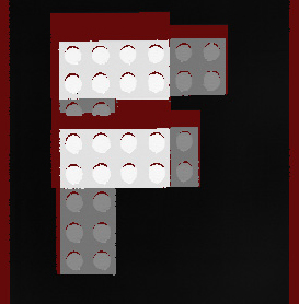
Generally, because the 4x EncoderResolution setting offers the greatest flexibility when setting up the distance between acquired range image lines, Cognex recommends that you use this setting. The 2x and 1x settings may be useful when you cannot achieve a large enough distance between two range image line acquisitions with the 4x setting.
Example:
DistancePerCycle = 0.08 mm/cycle
- Setting Steps per Line = 9 and EncoderResolution = 4x produces lines 0.18 mm apart.
- Setting Steps per Line = 15 and EncoderResolution = 4x produces lines 0.3 mm apart.
- Setting Steps per Line = 5 and EncoderResolution = 2x produces lines 0.2 mm apart.
- Setting Steps per Line = 8 and EncoderResolution = 2x produces lines 0.32 mm apart.
Set Resolution Parameters Including Scan Length, X Scale, and Y Scale
Scan Length in Pixel - Specify the number of rows a range image should contain, that is, the number of acquired lines of the laser stripe.
XScale and YScale - Set them for the range image to preserve aspect ratio. XScale and YScale correspond to the number of millimeters per column and row in the acquired range image, respectively. If you are in the Encoder or Simulated Encoder mode, YScale is a read-only value, automatically computed based on the DistancePerCycle, EncoderResolution, Steps per Line, and the encoder type settings. For features in the range image to appear with the same aspect ratio as they appear in the real world, set the XScale to the calculated YScale, or click the lock symbol beside the X Scale field to have it updated automatically to the YScale value.
Handle Encoder Overrun Errors
If the actual encoder settings (Steps per Line for example) cause the acquisition initiation of a line faster than the Line Time (the time needed to acquire an intensity image and process it to generate a range image line), you will get an encoder overrun error. This applies to separate encoders and the test encoder as well. An encoder overrun error causes red lines of missing pixels in the acquired range image in the wizard and it causes acquisition to be canceled in the Job. Therefore, make sure that the time for each Step is greater than the Line Time.
You can choose to ignore too fast encoder by making sure the Ignore Too Fast Encoder on the Advanced tab is checked on the wizard GUI (and setting IgnoreTooFastEncoder to true in the API). If you do so, in case the encoder would initiate a new line acquisition faster than the Line Time, the line for which there is not enough time to process will be substituted by a row of missing pixels in the range image acquired in the Job without generating an error or the acquisition being canceled. For detailed explanation on missing pixels, see the Hidden Areas section of the Working with 3D Range Images topic.
Select Output Image Type
CameraMode - You can change the image type to be acquired from QuickBuild to Intensity, Intensity with Graphics, or Range With Grey from the default Range image. For information on RangeWithGrey images, see the Working with 3D RangeWithGrey Images topic.Set range image properties, which control the characteristics of the generated range image, on the Range Image tab.
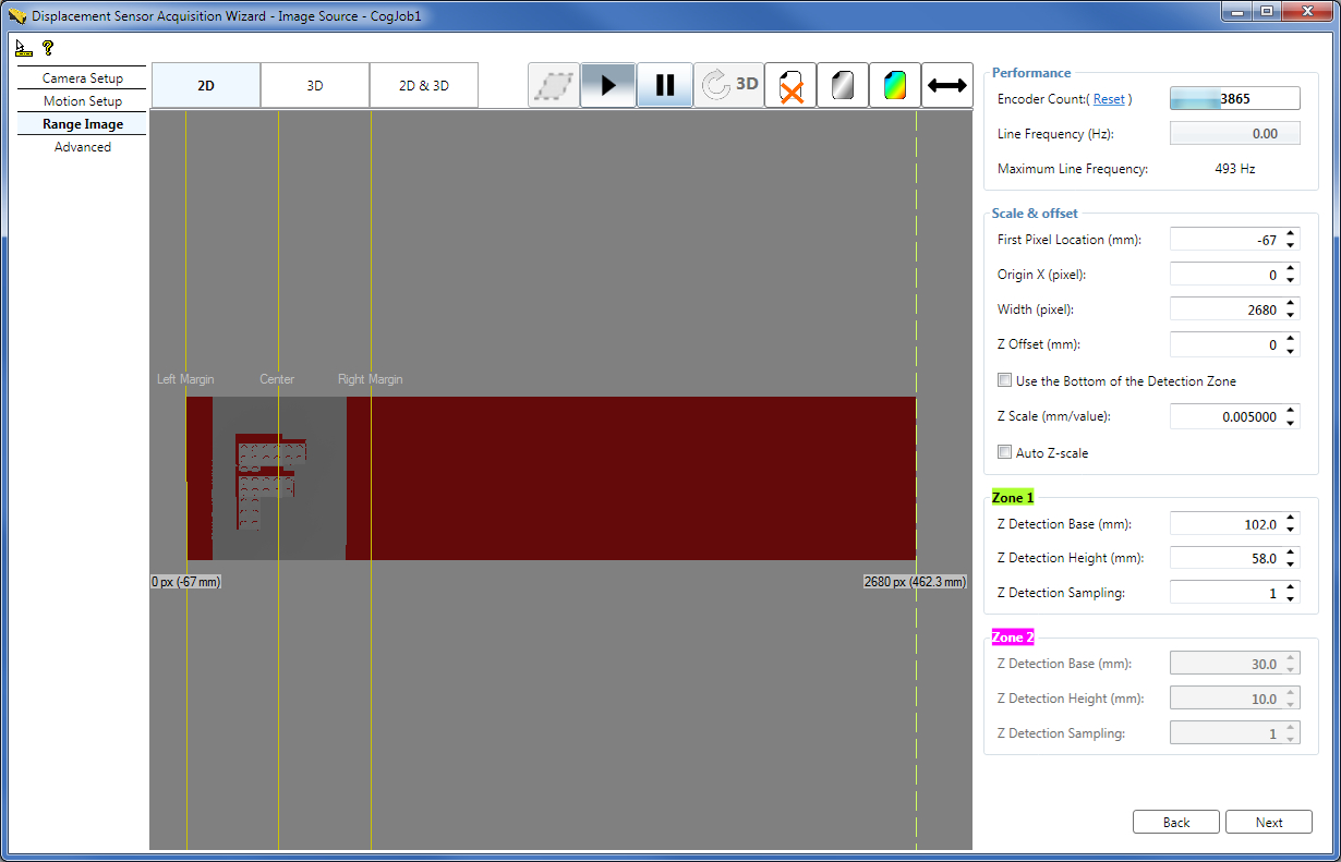
Set Range Image Properties while Acquiring Range Images in the Wizard
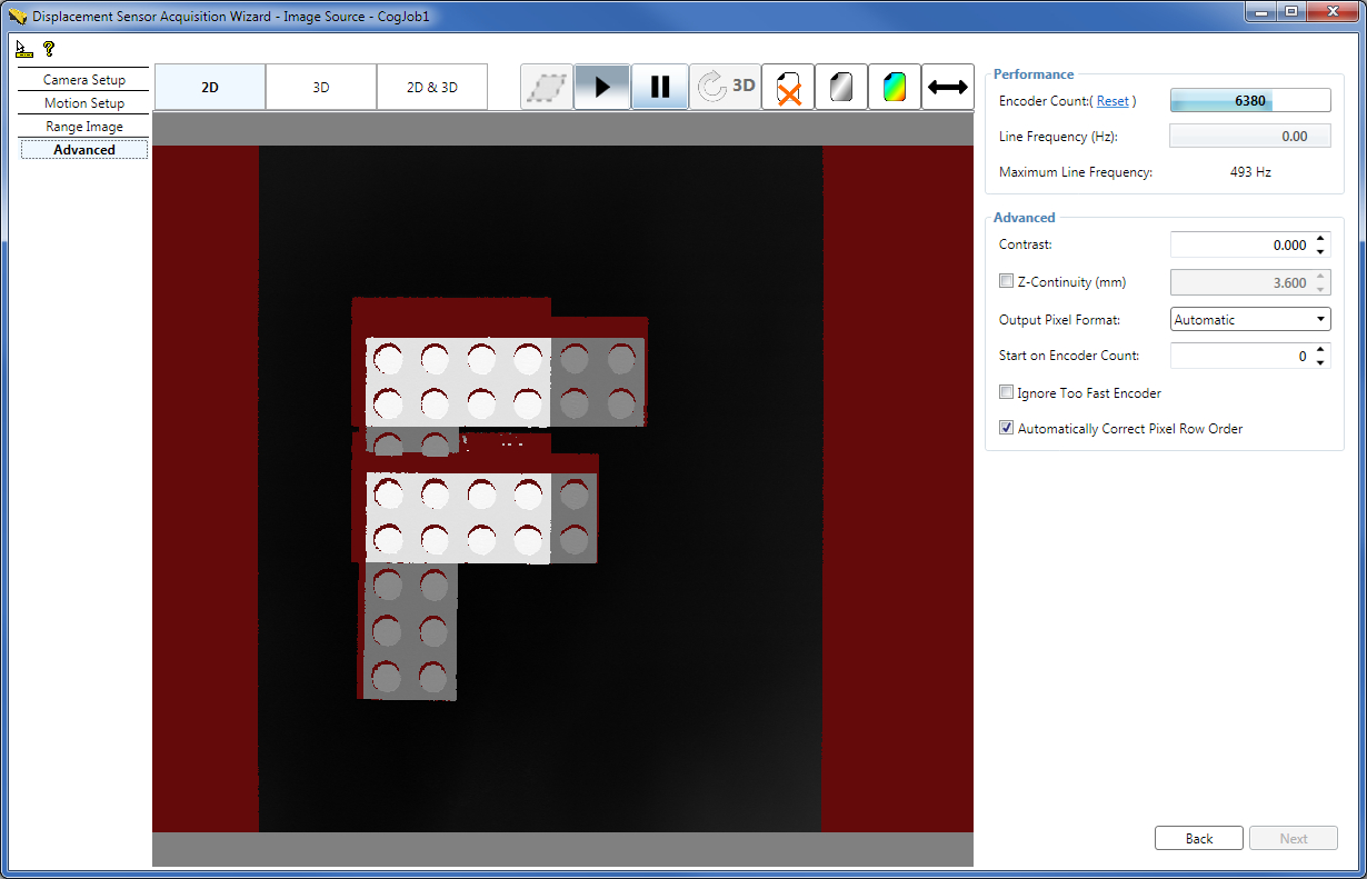
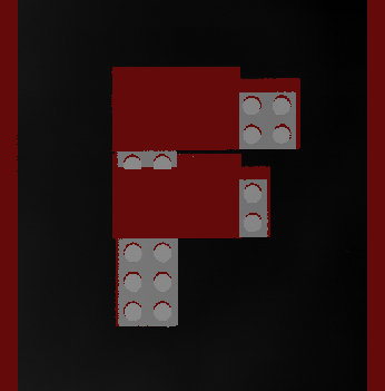
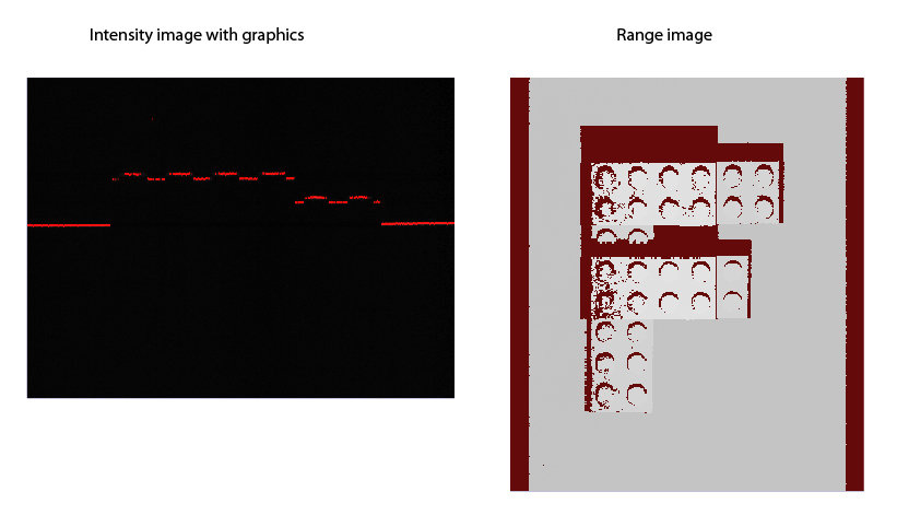
The following figure shows a range image acquired with the wizard about an F-shaped LEGO® block while the Colormap control was used to enhance the visible features of the range image by zooming into the height range that contains height changes. You can also enhance the visible features of the range image by using the Auto Z-scale feature described hereinafter.
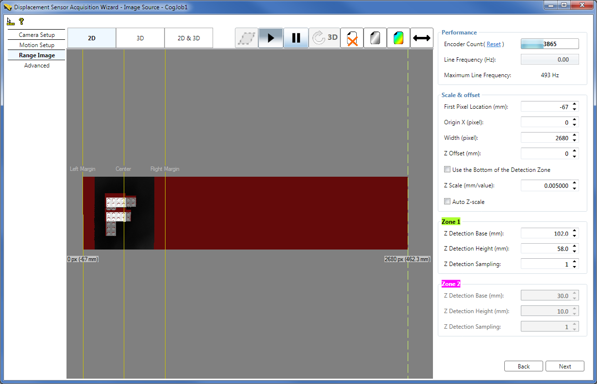
The Range Image tab displays the range image acquired using the wizard with the following guides:
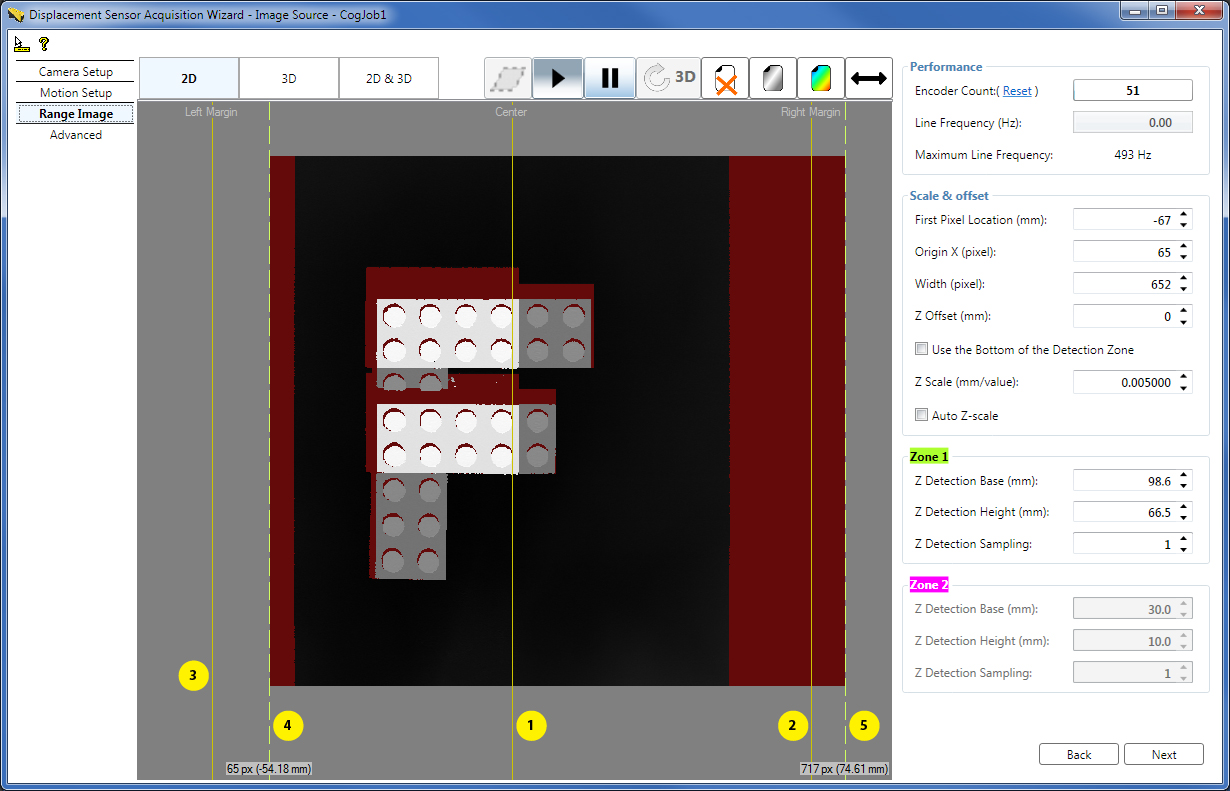
- 1 - Center line, marking the center of the Working Section (the origin of the X axis of the Sensor3D coordinate space) in the acquired range image. The Center line corresponds to the optical center of the sensor.
- 2 - Right Margin, marking in the acquired range image the maximum extent of the Working Section to the right viewed in the lens-to-laser direction (in the positive X-direction).
- 3 - Left Margin, marking in the acquired range image the maximum extent of the Working Section to the left viewed in the lens-to-laser direction (in the negative X-direction).
4 - Dashed range image first pixel indicator line on the left, marking the left border of the acquired range image, with the label:
Origin X px (Pixel location in mm to which the first pixel corresponds) Pixel location in mm to which the first pixel corresponds = FirstPixelLocation + Origin X * XScale When the Origin X is zero (default), the Pixel location in mm to which the first pixel corresponds equals the FirstPixelLocation parameter.Grab and move this indicator line to set the new left border of the range image. You can observe the effect of this adjustment in the new range image the wizard acquires.
By default, the first pixel indicator is at the same position as the Left Margin, that is, at the start of the Working Section. Therefore, the dashed line may not be visible being covered by the margin. In this case you can grab the guide by grabbing the common area of the guide and the Left Margin.
- 5 - Dashed range image last pixel indicator line on the right, marking the right border of the acquired range image, with the label:
Origin X + Width px (Pixel location in mm to which the last pixel corresponds)
Pixel location in mm to which the last pixel corresponds = FirstPixelLocation + (Origin X + Width) * XScale
Grab and move this indicator line to set the new right border of the range image. You can observe the effect of this adjustment in the new range image the wizard acquires.
By default, the last pixel indicator is at the same position as the Right Margin, that is, at the end of the Working Section. Therefore, the dashed line may not be visible being covered by the margin. In this case you can grab the guide by grabbing the common area of the guide and the Right Margin.
Width - You can specify the number of columns the range image should contain by using the Width field on the GUI as well.
Origin X - You can modify the X origin of the range image by using the Origin X field on the GUI as well.
In the API, you can specify the above parameters and the Scan Length in Pixel using the SetROIXYWidthHeight method of the ICogAcqFifo.OwnedROIParams property by passing the arguments in the following format: SetROIXYWidthHeight(int OriginX, 0, int Width, int ScanLengthInPixel)
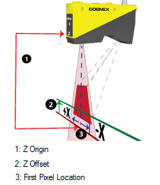
FirstPixelLocation - Specify the FirstPixelLocation which defines in mm the physical first pixel location of the range image along the X axis; that is, the location where the range image starts from the left.
FirstPixelLocation and Origin X usage when multiple sensors are used side by side to acquire wider images: These two setting allow you to adjust the coordinate space of the acquired image. For example, assume you have two cameras next to each other, mounted 80 mm apart, to acquire images of a wide part. You might set the first pixel location of the first camera to -50 mm, and the second camera to -130 mm (-50 mm - 80 mm), so that the first pixel location for both cameras corresponds to the same physical location. Origin X would be adjusted on camera 2 to skip the area covered by camera 1. This results in a situation where the real world coordinates of an image pixel will be relative to the same point for images taken with either camera, so you do not need to manually account for the 80 mm spacing between cameras.
ZScale and ZOffset - You use the ZScale range image parameter to specify in mm the scaling of pixel values. By default, the pixel value of 1 represents the height at the (Z Origin + 1 x ZScale) height. You may specify a custom height value (in mm) to correspond to the pixel value of 1 by using the ZOffset range image parameter, which is added to the Z Origin. Note that heights at Z Origin (or ZOffset) are also represented by the pixel value of 1 (instead of 0). See more in Range Image Coordinate Spaces and Associated Parameters. You can choose to use the bottom height of Zone 1 as the ZOffset by checking the Use the Bottom of the Detection Zone checkbox.
Auto Z-scale - You can enhance the visible features of the range image by zooming into the height range that contains height changes also by checking the Auto Z-scale checkbox, instead of (or in addition to) using the Colormap control. The new ZScale is calculated based on the range between the top of detection Zone 1 and ZOffset if only Zone 1 is used, and based on the range between the top of Zone 2 and ZOffset if both detection zones are enabled. It is recommended that you enable the Use the Bottom of the Detection Zone option when using the Auto Z-scale option. Note that in order for the new automatic ZScale to take effect, you have to acquire a new range image, in contrast with the Colormap control which can be applied to the current range image as well.
Zone 1 and Zone 2 - You can specify the tops, bottoms, and sampling for the detection zones Zone 1 and Zone 2 (described previously) numerically on this tab.
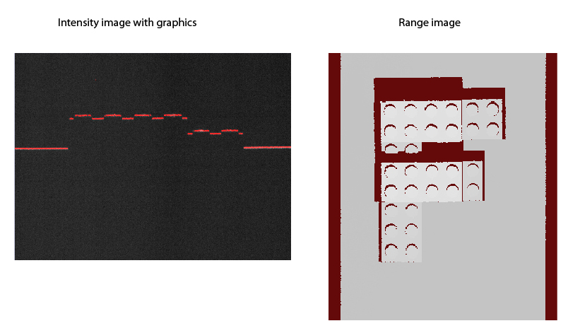
The resulting adjusted range image: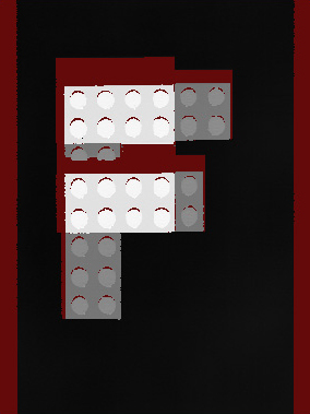
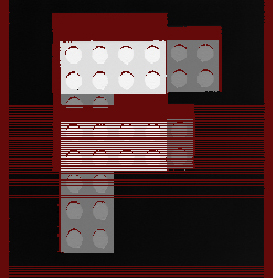
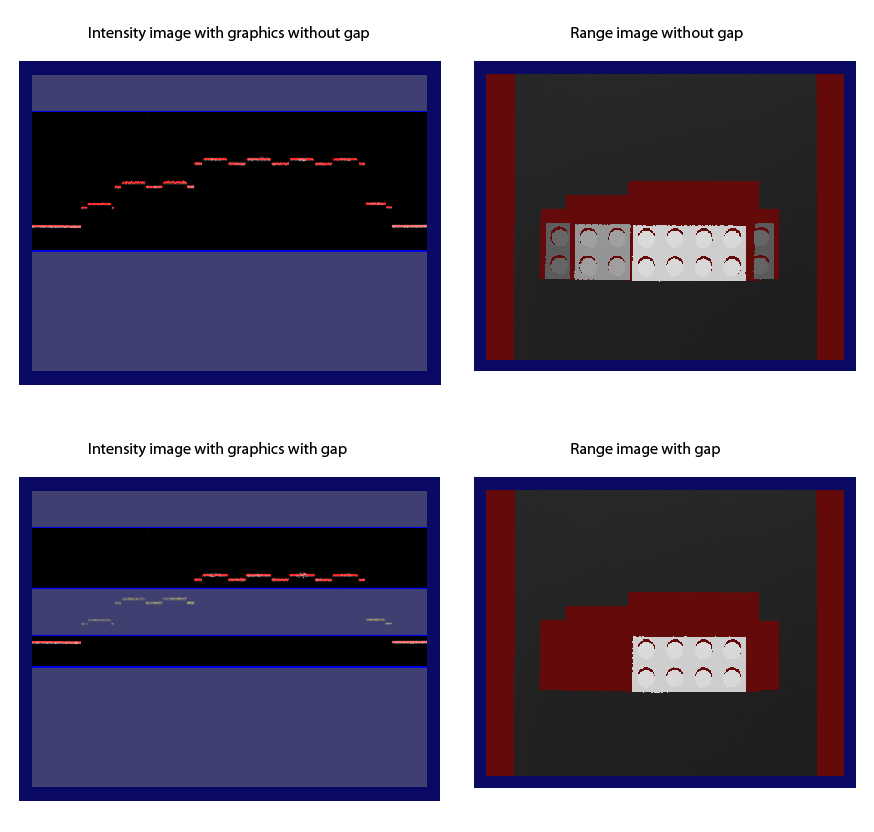
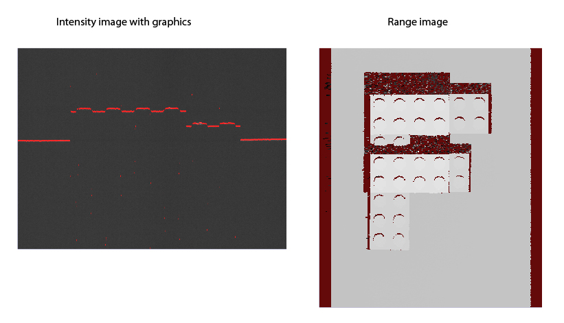
The following figure illustrates range image generation of an object with and without gap. These images were acquired from the Job, therefore, they do not contain the previously described guides.
Set advanced acquisition parameters on the Advanced tab. Typically, you do not need to change the parameters on this tab for most acquisition scenarios.
Contrast - If it becomes necessary to increase the Contrast value for the GigE camera (from the default of zero), you can increase it on this tab. The maximum contrast value is 1. You can verify whether your Contrast setting is appropriate either by looking at newly acquired range images on the Advanced tab or by switching to the Camera Setup tab and inspecting the intensity image with graphics.
ZContinuityThreshold - You can define the maximum height difference for adjacent range image pixels to be connected (and shown). Adjacent pixels with height difference greater than this threshold do not get connected and are therefore not shown (they are shown as missing pixels). For more information, see the Pixel Generation, Interpolation, and Missing Pixels section.
OutputPixelFormat - You can change the output pixel format of the acquired image, if needed. Automatic (default) - images are acquired in their default formats (for example, range images in the range image format and intensity images with graphics in RGB Planar format); Grey 8, Grey 16, RGB Planar - the acquisition system performs image type conversion to the given format and outputs the resulting image. Normally, changing this parameter is not needed.
StartAcqOnEncoderCount - If you are using a hardware TriggerModel (either auto or semi-auto), you can use StartAcqOnEncoderCount to change the location of the first line relative to where the trigger occurs. (You cannot use a negative value to acquire the first line before the trigger is received).
IgnoreTooFastEncoder - You can choose to ignore too fast encoder by making sure the Ignore Too Fast Encoder on the Advanced tab is checked on the wizard GUI (and setting IgnoreTooFastEncoder to true in the API). If you do so, in case the encoder would initiate a new line acquisition faster than the Line Time, the line for which there is not enough time to process will be substituted by a row of missing pixels in the range image acquired in the Job without generating an error or the acquisition being canceled.
AutoCorrectPixelRowOrder - Check the Automatically Correct Pixel Row Order checkbox (or set to true AutoCorrectPixelRowOrder from the API) to select automatically setting the row order of the acquired image to match the actual appearance of the scene. If this value is set to false, then images acquired in the laser-to-lens direction will have an inverted pixel row order (the image will appear mirrored top-to-bottom with respect to the actual appearance of the scene).
On the Calibration tab of the Image Source GUI, you can
- Enable and configure field calibration. For information on setting up acquisition with your DS1000 series sensor using field calibration, see the DS1000 Acquisition Using Field Calibration topic.
- Select the Primary Space Name 3D.
- Select the Primary Space Name 2D and set it as the selected space.
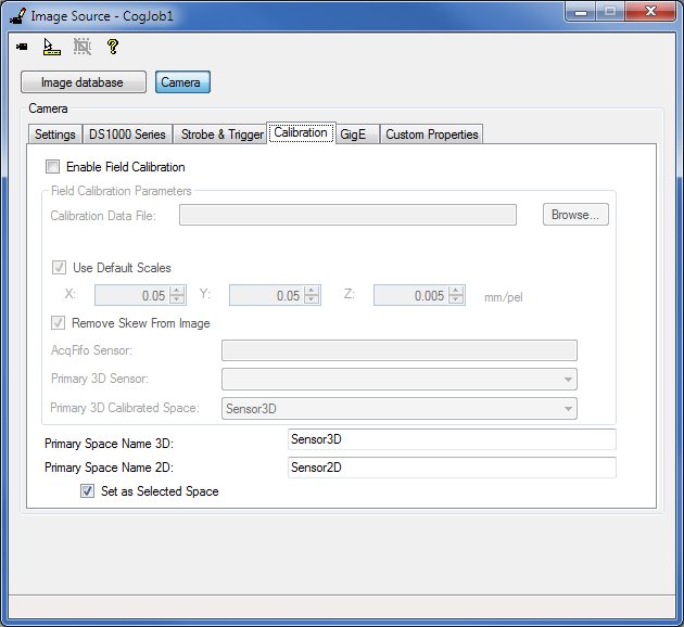
If field calibration is disabled, the Primary Space Name 3D corresponds to the factory calibrated 3D space that is used to render the pixels in the (factory calibrated) range image. This is by default the Sensor3D space. If field calibration is enabled, the Primary Space Name 3D corresponds to the field calibrated Primary 3D Calibrated Space, used to render the pixels in the field calibrated range image. Primary Space Name 3D is set as the selected 3D space name in the 3D coordinate space tree of the acquired range image. If Remove Skew From Image is set to true, the acquired range image is rendered in the selected 3D space name (using field calibration correction), that is, in the Primary Space Name 3D. You can give a custom value to the Primary Space Name 3D.
The space defined by Primary Space Name 2D is a 2D space that corresponds to the Z=0 plane in the space defined by Primary Space Name 3D. Primary Space Name 2D will be added to the 2D coordinate space tree of the acquired range image. This space can be used with 2D vision tools to obtain calibrated real-world measurements. The default name for this space is Sensor2D and it is set as the selected 2D space for acquired images. You can also give a different name for the Sensor2D space on this tab, and you can prevent the space from being the selected 2D space by unchecking the Set as Selected Space checkbox. For more information on the Sensor2D Space, see the Using 2D Vision Tools with Range Images topic.
If you are using QuickBuild, close the wizard and start acquiring range images from the Job. If you want to acquire range images manually, for example, press the Run button for the Job to acquire an initial range image. You can acquire range images from the sensor from the Job as you would acquire from any other camera.
If you want to use different acquisition settings, stop the acquisition and then launch the wizard and set the new acquisition parameters. Once done, close the wizard and start acquiring again.
Note that simultaneous acquisition from the Job and the wizard is not supported.
This section contains the following subsections.
- Optimize for Speed
- Optimize for Resolution along the Z Axis
- Optimize for Resolution along the Y Axis
- Optimize for Resolution along the X Axis
- Setting the Acquisition Parameters based on Concrete Resolution Requirements while Preserving Aspect Ratio
Perform further adjustments to achieve a certain performance result.
If your acquisition speed is higher than what your current parameter set supports causing encoder overruns, you need to optimize your parameters for speed.
The following figure shows a range image that was acquired with the conveyor belt travelling too fast, which as a result has encoder overruns showing up as lines of missing pixels (to avoid acquisition from the Job to be stopped by encoder overruns, select the IgnoreTooFastEncoder option):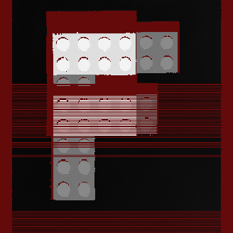
Adjust Z Detection Parameters for Speed Improvement
Adjust the ZDetectionBase and ZDetectionHeight parameters (of Zone 1) to exclude from the detection as much of the heights that you do not want to detect as possible. There is less data in the reduced Working Section of Interest that the DS1000 series sensor needs to process to create a range image line, reducing the Intensity Image Processing Time, which may reduce the Line Time.
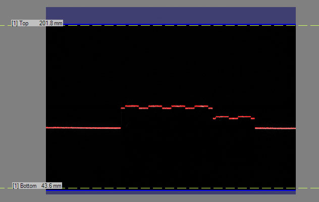
The following images show the optimized and a non-optimal Working Section of Interest settings: Optimized settings: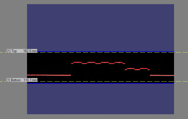
You can also increase the ZDetectionSampling parameter to increase the interval between processed intensity image rows and thereby decreasing the total number of rows the sensor needs to process for a range image line, resulting in a decreased Intensity Image Processing Time, which may result in a decreased range image Line Time. However, this will decrease accuracy along the Z axis.
If you have a height range in which you are not interested, you may want to use Zone 2 in addition to Zone 1 such that Zone 1 detects the lower height ranges of interest and Zone 2 detects the higher height ranges of interest. The gap between the two zones is not processed which decreases the Intensity Image Processing Time and therefore may decrease the Line Time and may increase the Maximum Line Frequency. You adjust the ZDetectionBase2 and ZDetectionHeight2 parameters for Zone 2.
You can also set the Line Finding Mode (LaserDetectionMode in the API) to Fast if you want to increase the Maximum Line Frequency at the cost of accuracy (if the Intensity Image Processing Time is greater than the Exposure time). Standard mode is the default. Also, Fast mode allows for the reduction in Exposure time, for the reduction in accuracy. For an even greater increase in the Maximum Line Frequency than what the Fast mode provides (at an even greater cost of accuracy), you can set the Line Finding Mode to Binary.
You can set the PeakDetectionMode to Max instead of Closest or Farthest, which may slightly increase the Maximum Line Frequency by possibly decreasing the Intensity Image Processing Time.
Place Your Objects under Inspection Lower or Mount Your DS1000 Series Sensor Higher and Readjust the Z Detection Base Parameter
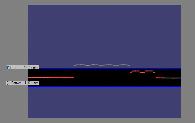
At the cost of resolution along the Z axis and the X axis, you may be able to increase your acquisition speed by placing your objects under inspection lower relative to the DS1000 series sensor or the sensor higher relative to your objects. The features of the objects under inspection will correspond to fewer rows (and columns) in the camera of the sensor and therefore appear smaller in the intensity image. The reduced number of rows will result in a decreased Intensity Image Processing Time, which may reduce the Line Time and increase the acquisition speed. Make sure you readjust your ZDetectionBase to the new base height. The ZDetectionHeight parameter should be left unchanged for the same object sizes because it is specified along the Z axis of the Working Section and in mm (and not in camera pixels). However, the area that corresponds to the ZDetectionHeight in the intensity image with graphics will appear smaller after reducing the ZDetectionBase.
For the illustration of the resolution change along the X and Z axes, see the Range Image Coordinate Spaces and Associated Parameters topic.Decrease the Exposure Time for Speed Improvement
You can decrease the Exposure time to decrease the Line Time (if the Exposure time is greater than the Intensity Image Processing Time). Because the intensity of the laser in the intensity image decreases as a result, for reliable detection, it is recommended that you increase the Contrast (on the Advanced tab) and/or the laser DetectionSensitivity. If the increased Contrast and laser DetectionSensitivity levels cause image noise that you do not want to be present, decrease the laser DetectionSensitivity and if necessary increase the Contrast.
With these settings, you should achieve a correct-looking intensity image with graphics as discussed previously in the section about low-level acquisition control parameters. Once you have achieved a correct-looking intensity image or intensity image with graphics, acquire a range image and verify that there are no more encoder overruns and your range image looks correct.The following images show the result of decreased Exposure time:
If HighDynamicRange is selected, the whole exposure time is greater than the original Exposure time, plus there is need for an additional original (non-HighDynamicRange) Intensity Image Processing Time to process the intensity image. As a result, the Line Time will increase. If you used but do not need HighDynamicRange for your application anymore, you can disable it to decrease the Line Time.
Increase the Steps per Line Parameter and/or Decrease the Resolution for Significant Speed Improvement
At the cost of resolution loss along the Y axis (and the X axis if you are preserving aspect ratio by keeping XScale the same as YScale), you can increase your acquisition speed by sampling your object under inspection less frequently. You can achieve this by increasing the Steps per Line and/or decrease the EncoderResolution. Make sure your XScale is readjusted to the new YScale if you are preserving aspect ratio.
You may also elect to keep your X resolution at the same level (by retaining XScale) while decreasing the Y resolution for speed. In this case, the range image will appear distorted (in the pixel space). However, the 3D transform (and 2D transform) contained in the range image ensures that pixel locations in the range image correspond to the correct positions in the physical Sensor3D Space (and Sensor2D Space). In other words, the 3D transform (and 2D transform) allows you to get accurate feature positions and sizes, even though the range image appears distorted.
These settings do not change the Line Time.If you want your objects to be inspected with higher resolution along the Z axis, you can place your objects under inspection higher relative to the DS1000 series sensor or your sensor lower relative to your objects. This way, the features of the objects under inspection will correspond to more rows (and columns) in the camera of the sensor and therefore appear bigger in the intensity image, resulting in higher resolution. Make sure you readjust your ZDetectionBase to the new base height. The ZDetectionHeight parameter should be left unchanged for the same object sizes because it is specified along the Z axis of the Working Section and in mm (and not in camera pixels). However, the area that corresponds to the ZDetectionHeight in the intensity image with graphics will appear larger after increasing the ZDetectionBase. The increased number of intensity image rows will result in the increase of the Intensity Image Processing Time, which may increase the Line Time and reduce the acquisition speed.
If you have Zone 2 enabled and it is linked to Zone 1, then the position of Zone 2 will automatically be readjusted when readjusting the ZDetectionBase parameter. If it is not linked, make sure you readjust the ZDetectionBase2 parameter also, with the same amount you readjusted the ZDetectionBase. For the illustration of the resolution change along the X and Z axes, see the Range Image Coordinate Spaces and Associated Parameters topic.Set the Line Finding Mode (LaserDetectionMode in the API) to the default Standard (if you had Fast or Binary mode set) to increase accuracy at the possible cost of Maximum Line Frequency.
Enable High Dynamic Range for Surfaces with Varying Reflectivities
Optimum Z accuracy is achieved when the laser lines are visible, but not bright saturated. Some scenes exhibit different reflectivities or different surface normals which cause different portions of the scene to appear brighter or darker. For these scenes, it may be difficult to find an exposure setting which causes all the features to be simultaneously visible, but not bright saturated. The HighDynamicRange switch is designed for these cases. When HighDynamicRange is enabled, two intensity images are acquired for each trigger: one acquisition at one tenth of the specified Exposure, followed by another acquisition at the specified Exposure. Then, the peak detection algorithm is run for both acquired intensity images; and, for each column of the intensity images, the detected peak corresponding to the shorter exposure is kept to generate a column of the raw peak data. When HighDynamicRange is enabled, the shorter exposure prevents the bright areas from saturating the pixels.
- If there is a single exposure which induces (a) all features’ peaks to be detected and (b) all features are not bright saturated, then that exposure will induce optimum Z accuracy.
- If there is no single exposure which induces (a) all features’ peaks to be detected and (b) all features are not bright saturated, then the HighDynamicRange mode should be enabled.
Note that enabling HighDynamicRange will reduce the Maximum Line Frequency.
Notes on using HighDynamicRange with RangeWithGrey images:
- Enabling HighDynamicRange produces larger values in the grey data portion of a RangeWithGrey image, as it increases the dynamic range of the image (10 fold).
- Better grey data is achieved with a higher DetectionSensitivity. Ideally, the DetectionSensitivity should be set such that the switchover from using the short exposure to the long exposure occurs just as the pixels in the longer exposure are coming out of over saturation (the purple pixels become green as the DetectionSensitivity is being increased).
For display purposes, ZOffset and ZScale can be adjusted such that the range of pixel values in the range data roughly corresponds to the range of pixel values in the grey data. This allows one Colormap setting to be used for easy viewing of both range and grey data.
The grey data looks the best when the Colormap goes all the way to 0, so black really looks black. ZOffset can be adjusted such that the lowest areas of the range data have a pixel value near 0.
The upper limit of the Y resolution is the minimum distance along the Y axis between two range image lines that the acquisition system can acquire. The upper limit of the Y resolution equals the distance travelled by your conveyor belt during two encoder Steps (at maximum EncoderResolution setting).
You can do the following to increase the Y resolution.
Increase the Encoder Resolution and Decrease the Steps per Line Parameters
To increase the Y resolution, you can increase the EncoderResolution. Its recommended values are 2x or 4x (4x is the maximum). You can also decrease the Steps per Line parameter (the minimum value is 2).
If you increase the Y resolution, range image lines will be acquired more frequently, which may result in encoder overruns if the time that elapses between two encoder counts is less than the Line Time. In this case, you can either reduce the speed of the conveyor belt or optimize for speed by adjusting low-level acquisition control parameters (including Z detection parameters, exposure, and contrast settings).
If you want to preserve aspect ratio, make sure XScale is readjusted to the new YScale.
The following figure shows range images: one acquired using 15 Steps per Line and 4x EncoderResolution and an optimized one using 5 Steps per Line and the same 4x EncoderResolution:
Change Encoder Mounting if the Y Resolution Upper Limit Is Not Sufficient
If the upper limit of the Y resolution (the distance travelled during two encoder steps) is not sufficient and you want to decrease this distance, you can either change the transmission of the encoder or use a different encoder type that produces more counts at the same distance.
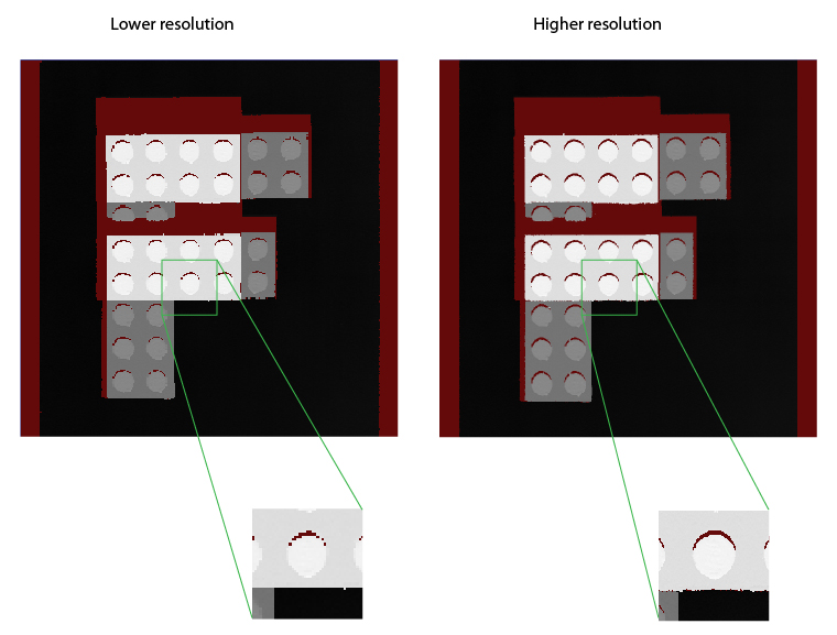
You may want to increase your X resolution either by increasing the sampling rate along the X axis or, if the sampling rate is otherwise sufficient, increase the displayed resolution.
If You Need Higher X Sampling Rate, Place Your Objects under Inspection Higher or Mount Your DS1000 Series Sensor Lower and Readjust the Z Detection Base Parameter
If you want your objects to be inspected with higher resolution along the X axis, you can place your objects under inspection higher relative to the DS1000 series sensor or your sensor lower relative to your objects. This way, the features of the objects under inspection will correspond to more columns (and rows) in the camera of the sensor and therefore appear bigger in the intensity image, resulting in higher resolution. Make sure you readjust your ZDetectionBase to the new base height. The ZDetectionHeight parameter should be left unchanged for the same object sizes because it is specified along the Z axis of the Working Section and in mm (and not in camera pixels). However, the area that corresponds to the ZDetectionHeight in the intensity image with graphics will appear larger after increasing the ZDetectionBase. The increased number of intensity image rows will result in the increase of the Intensity Image Processing Time, which may increase the Line Time and reduce the acquisition speed.
If the Sampling Rate is otherwise Sufficient, Decrease the X Scale to Increase the Displayed X Resolution
The displayed X resolution is the inverse of the XScale parameter. If your current X resolution is not sufficient while you have been preserving aspect ratio until now and your acquisition setup limits your X resolution through limiting the Y resolution, you may elect not to preserve aspect ratio and decrease the XScale parameter to increase the X resolution. You can achieve real resolution increase (that is, object features appearing with more details in the acquired range image) as long as you do not oversample the intensity image. After reaching and exceeding the sampling rate with the displayed X resolution, newly generated pixels will not reveal more information about the object, they will be the duplicates of neighboring pixels.
Note that as decreasing the XScale parameter will result in more pixels generated along the X axis, make sure you increase your Width X setting, if needed, to accommodate the greater number of pixels generated. Also note that the 3D transform (and 2D transform) contained in the range image ensures that pixel locations in the range image, even if distorted by different X and Y scales, correspond to the correct positions in the physical Sensor3D Space (and the Sensor2D Space). In other words, the 3D transform (and 2D transform) allows you to get accurate feature positions and sizes, even though the range image appears distorted. For the illustration of the resolution change along the X and Z axes, see the Range Image Coordinate Spaces and Associated Parameters topic.In your application, you may have concrete resolution requirements resulting in concrete pixel size requirements. The following procedure is recommended to set the acquisition parameters based on concrete resolution requirements while preserving aspect ratio:
-
Choose a target pixel size. This can be done by several methods.
Method 1
Pick a size based on the characteristics of the part and desired size of the acquired image. For example, if the part does not have features finer than 1 mm, it is approximately 80 mm across, and you want a 400 pixel wide image, choosing a pixel size of 0.25 mm will produce an image 100 mm wide that has enough detail for the part, and also allows the full part to fit into the image.
Method 2
Compute the scale based on the camera’s approximate pixel size at a specified working distance. This can be computed as follows:
- pixel size = width / SensorResolution
- width = relative distance * (FarWidth - NearWidth) + NearWidth
- relative distance = (distance from camera - NearDist) / (FarDist - NearDist)
For the DS1100 model of the DS1000 series sensors, SensorResolution = 1024, FarWidth = 132, NearWidth = 60, FarDist = 315, NearDist = 140. So to compute the approximate pixel size at a distance of 200 mm from the camera, calculate the following (with some rounding):
- relative distance = (200 - 140) / (315 - 140) = 0.343
- width = 0.343 * (132 - 60) + 60 = 84.69 mm
- pixel size = 84.69 / 1024 = 0.083 mm/pixel
Method 3
Determine the pixel size based on the speed requirements of the application. For example, if the objects are moving under the camera at 1 meter per second, and the camera has a maximum rate of 1000 profiles per second, then attempting to acquire at a Y resolution of greater than 1mm/pixel will cause encoder overrun errors.
Configure the encoder settings to get as close as possible to the target pixel size. Assuming you have an encoder with 2048 pulses/revolution with a 10 mm wheel attached, the distance traveled per pulse is:
pi * 10 mm / 2048 = 0.0153 mm/tick
Assuming you want 0.083 mm/pixel, that is 0.083 / 0.0153 = 5.41 tics/pixel, you can get the closest to this by setting the Steps per Line value to 5 and the encoder Resolution value to 4x. Note that unless the Steps per Line value gets larger than what the hardware supports, there is no reason to use an encoder Resolution value other than 4x.Note that once you have specified the distance per tick via the linescan API, you can adjust the encoder Resolution and Steps per Line values, and the resulting YScale (in the range image API) will automatically be calculated.
- Set the XScale to match the actual YScale that was achieved. In this case, 5 steps per line at 0.0153 mm/tic = 0.0765 mm/pixel, as compared to the target scale of 0.083. This will produce pixels representing square shaped areas in the range image. Alternatively, if you wish to err on the side of finer resolution than desired, you can choose using 4 steps per line and an XScale of 0.0612, which would produce slightly smaller pixels.
This section summarizes the interfaces for some of the features of the DS1000 series sensors supported through VisionPro.
| Category | Interface | ||||||||||||||||||||||||
Line Scan Properties |
| ||||||||||||||||||||||||
GigE Vision Transport Properties | ICogAcqGigEVisionTransport |
| |||||||||||||||||||||||
Range Image Properties | ICogAcqRangeImage |
| |||||||||||||||||||||||
Camera Properties of DS1000 Series Sensors | ICogAcqProfileCamera |
| |||||||||||||||||||||||
Trigger Model Properties | ICogAcqTrigger |
|
Be aware that you cannot load an existing application where the following are true:
- The application uses 3D sensors that are not listed first in the frame grabbers list.
- The number of 3D sensors is less than allowed by the licenses your system currently uses