This topic contains the following sections.
Use a 3D displacement sensor to generate height-profile information about three-dimensional objects that cannot be easily generated by cameras that acquire two-dimensional cameras. A displacement sensor creates a synthetic range image that can be analyzed by other 3D vision tools to generate information about a planar surface, to generate height or volume calculation, or to analyze a cross-section of the object. The image can also be passed to any number of traditional vision tools to perform tasks such as pattern matching or optical character recognition.
For more information on range images, see the Working with 3D Range Images topic. For detailed information on range image acquisition, see the Acquiring Images from a DS900 Series Sensor and Acquiring Images from a DS1000 Series Sensor topics. For hardware-related information (such as mounting and physical product features) and further product details, see the DS900 Quick Reference Guide, the DS1000 Quick Reference Guide and the DS1000 Technical Reference Manual.
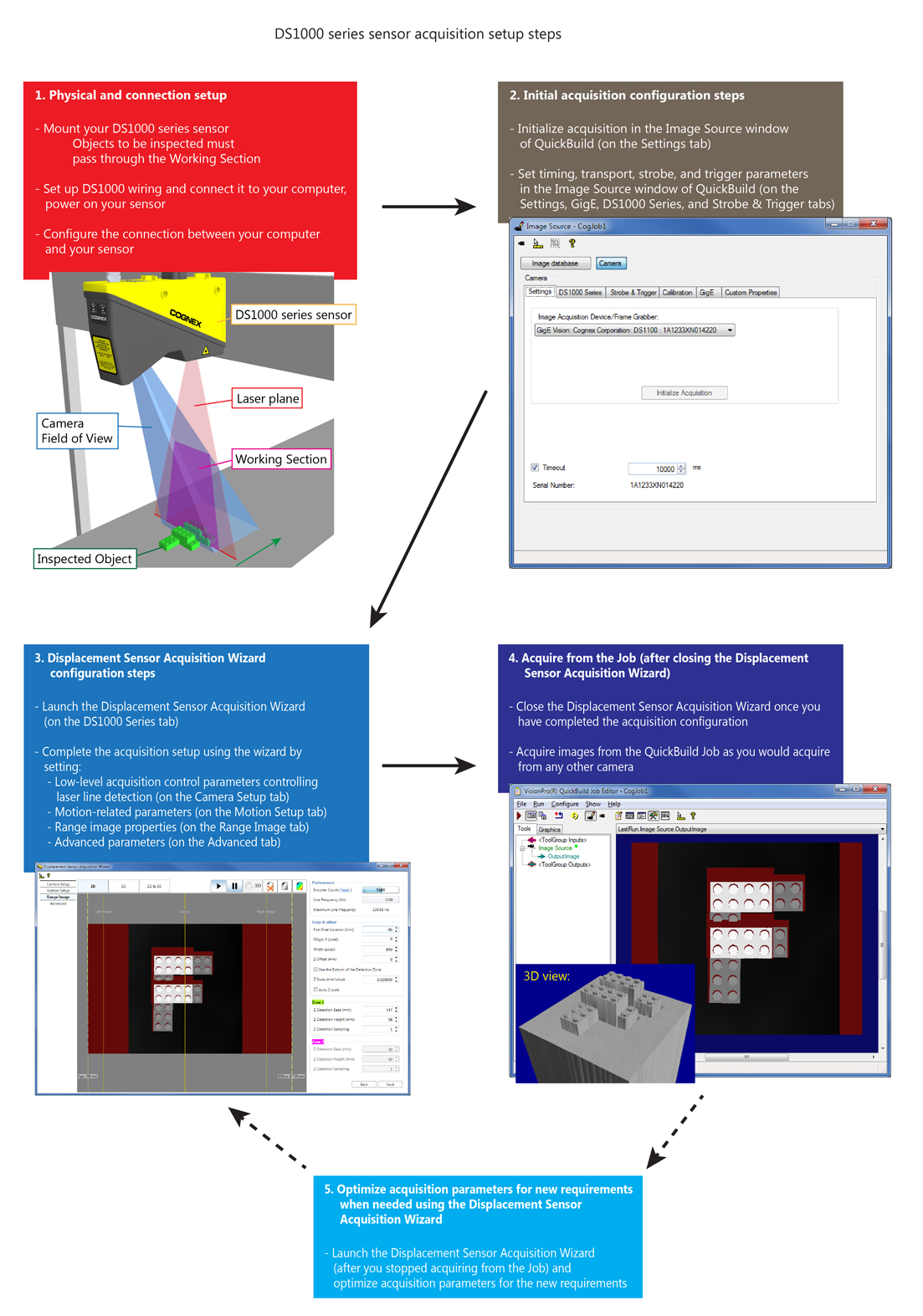
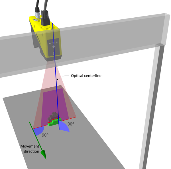
The following figure outlines the acquisition setup for a DS1000 series sensor.
Note: The acquisition setup is similar for the DS900 series sensor. For more information about the physical and connection setup, see the DS900 Quick Reference Guide, and the Acquiring Images from a DS900 Series Sensor topic for information about the initial acquisition configuration steps for the DS900.
This section describes the Displacement Sensor Acquisition Wizard. The Displacement Sensor Acquisition Wizard helps you set up your sensor easily, containing most displacement sensor-related parameters. You can navigate through the tabs of the wizard either by clicking them or by clicking Next or Back on the current tab. For the detailed descriptions and setting recommendations for these parameters, see the Acquiring Images from a DS900 Series Sensor and Acquiring Images from a DS1000 Series Sensor topics.
The wizard offers the same context menu options for displayed images as does the image display of a QuickBuild Job (available through right-clicking the image), such as the zoom, pan, and image fit options.
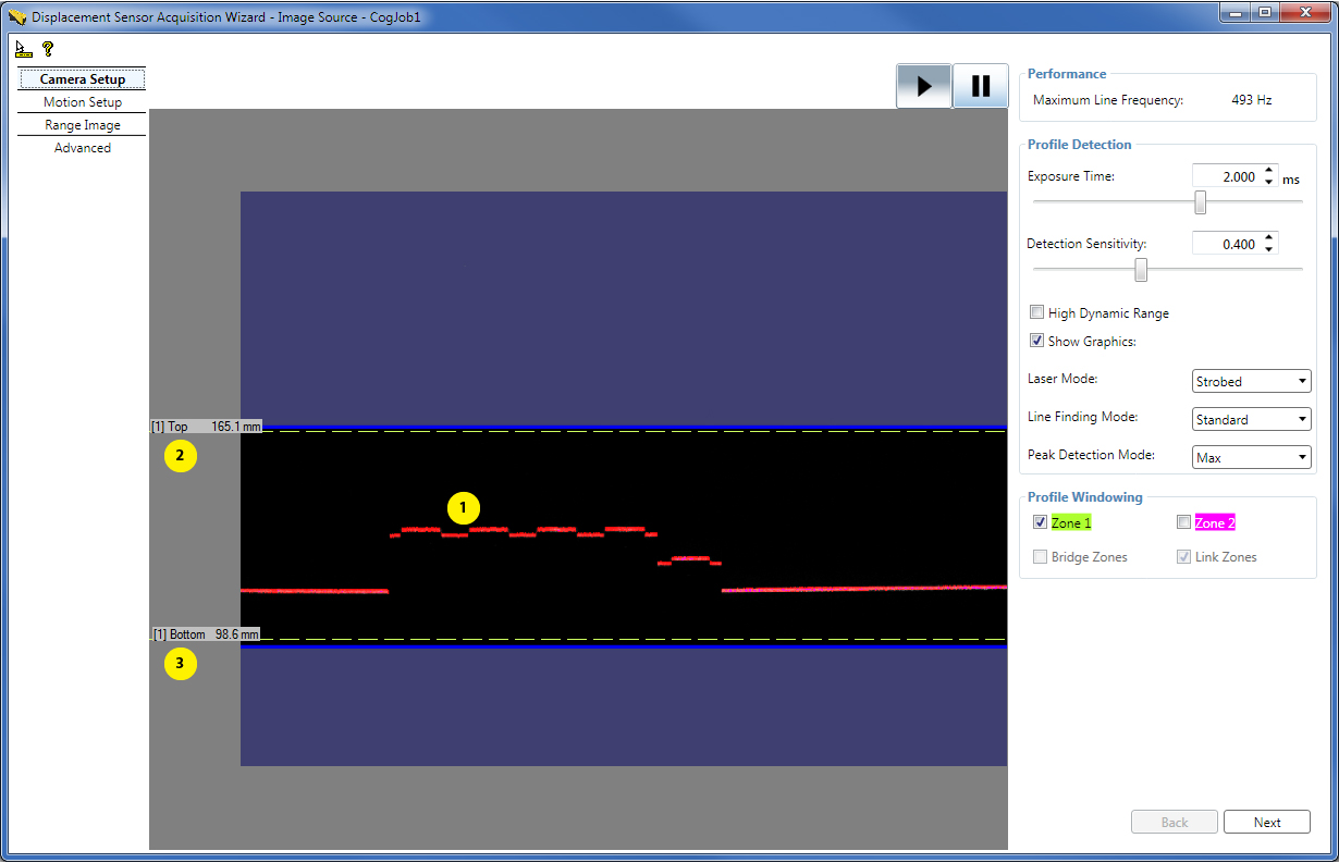
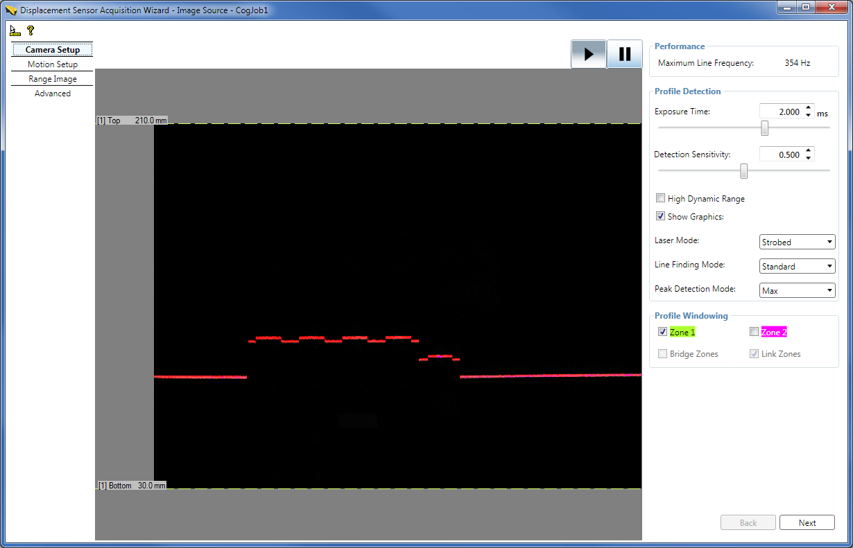
The Camera Setup tab continuously displays the intensity image the GigE camera sees with the graphics that displays the line finding results (1). It contains most low-level acquisition control parameters including the top (2) and bottom (3) selectors of the Working Section of Interest, which is the portion of the Working Section in which line finding is performed. (Laser line finding may be referred to as bright stripe curve finding elsewhere.) It also displays the Maximum Line Frequency for the current settings, directly read from the displacement sensor. You can also pause and continue the acquisition with the Pause and Play buttons.
The Motion Setup tab continuously displays the range image being acquired by the sensor (1). The range image is displayed as a waterfall image, small range image portions are acquired and added continuously to the displayed range image. This tab contains parameters related to the motion underneath the sensor, such as encoder settings and X and Y scale settings, and the camera mode defining the output image type. A typical scenario is inspecting objects passing underneath the sensor travelling on a conveyor belt.
To:- Pause or resume range image acquisition from the current position, click the pause (||) or resume/play (>) buttons (2).
- Restart range image acquisition from the current position, click Reset next to the Encoder Count field (3).
- Erase the currently displayed range image, click the erase button (X) (4).
- Select grey or colored tune for the range image displayed in the wizard, click the grey tune or the colored tune button (5).
- Resize the range image to fit into the current maximum horizontal Working Section, click the resize to Working Section button (6).
- Remove the skew (present due to sensor misalignment) from the acquired (2D) waterfall image, click the deskew button (//) (7). This button is only active when field calibration has been enabled (because field calibration results are used to remove skew distortion, stored in the calibration data file). By default, without clicking the deskew button, the acquired waterfall image is not corrected using the field calibration results. If you click the deskew button, waterfall image acquisition will stop. To restart waterfall image acquisition, click the play button. Note that if you have acquired a RangeWithGrey waterfall image, clicking deskew will result in a deskewed range image (and not a deskewed RangeWithGrey image).
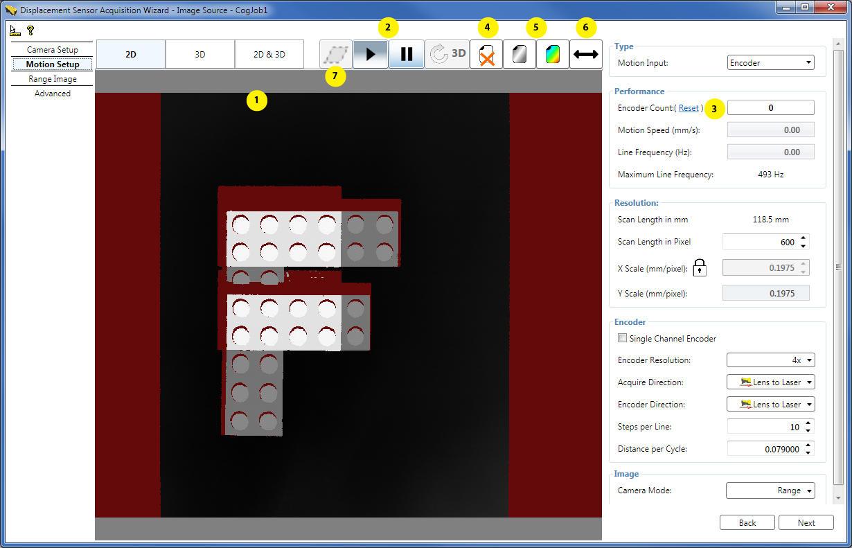
In a scenario with back and forth motion, if a dual channel encoder is used, the system keeps track of the backwards motion, and the waterfall image acquisition will not resume until either the forward motion has returned to the point where backwards motion began or Reset is pressed.
Viewing Range Images in 3D
You can view the range image acquired in the wizard also in the 3D viewer of the wizard (1) either by clicking the 3D button (2) to view it in 3D or the 2D & 3D button to view it in 2D and 3D at the same time.
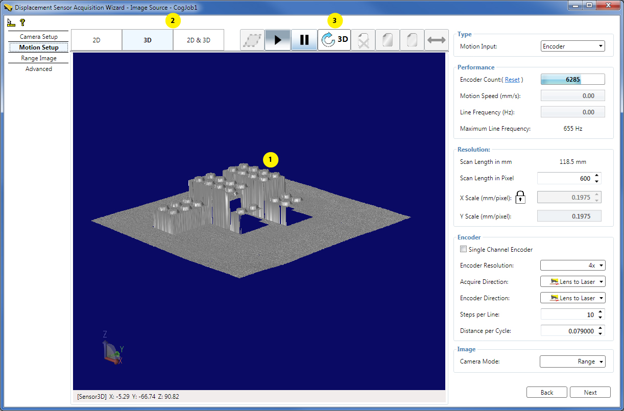
If your 3D display needs to be refreshed, click the 3D refresh button (3).
If you choose to acquire RangeWithGrey images (in the Camera Mode setting), the 3D display will automatically overlay the greyscale image on top of the range image.
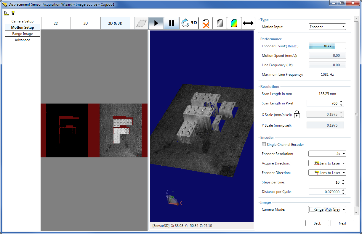
If you are using field calibration, the 3D viewer of the wizard displays the 3D image corrected by the field calibration results (in the 3D calibrated space selected on the Calibration tab).
Note: For more information, see the Viewing 3D Range Images with the 3D Viewer topic about the Cognex standalone 3D Viewer, and the Adding a 3D Viewer to Your Application topic about the control provided to programmatically visualize range images.
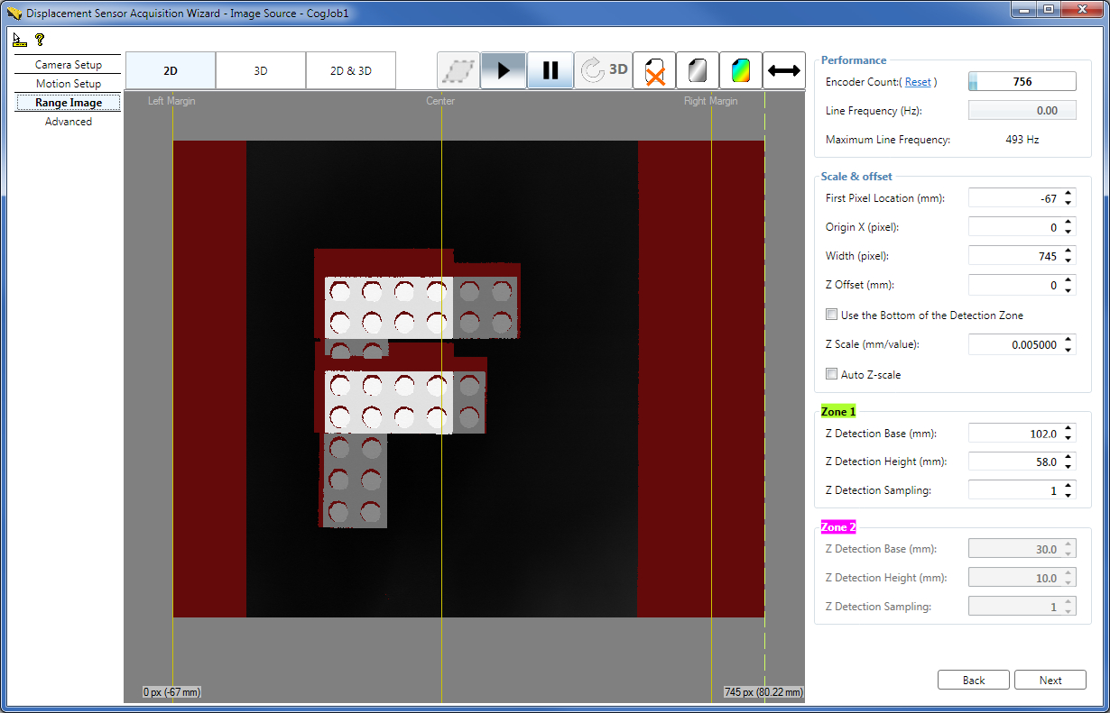
The Range Image tab continuously displays the range image being acquired by the sensor with the guides that define further main range image parameters, including image width, the location of the first pixel of the range image, origin offset, and height scaling.
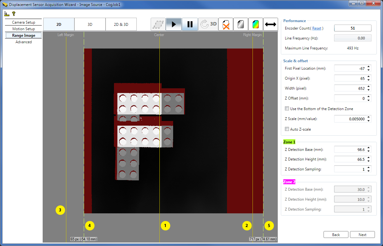
- (1) Center line, marking the center of the Working Section in the acquired range image.
- (2) Right Margin, marking in the acquired range image the maximum extent of the Working Section to the right viewed in the lens-to-laser direction.
- (3) Left Margin, marking in the acquired range image the maximum extent of the Working Section to the left viewed in the lens-to-laser direction.
- (4) Dashed range image first pixel indicator line on the left, marking the left border of the acquired range image. You can grab and move this guide. Note that by default, the first pixel indicator is at the same position as the Left Margin, that is, at the start of the Working Section. Therefore, the dashed line may not be visible being covered by the margin. In this case you can grab the guide by grabbing the common area of the guide and the Left Margin.
- (5) Dashed range image last pixel indicator line on the right, marking the right border of the acquired range image. You can grab and move this guide. Note that by default, the last pixel indicator is at the same position as the Right Margin, that is, at the end of the Working Section. Therefore, the dashed line may not be visible being covered by the margin. In this case you can grab the guide by grabbing the common area of the guide and the Right Margin.
You can also define the parameters numerically for the Working Section of Interest here, which is defined by the zone parameters.
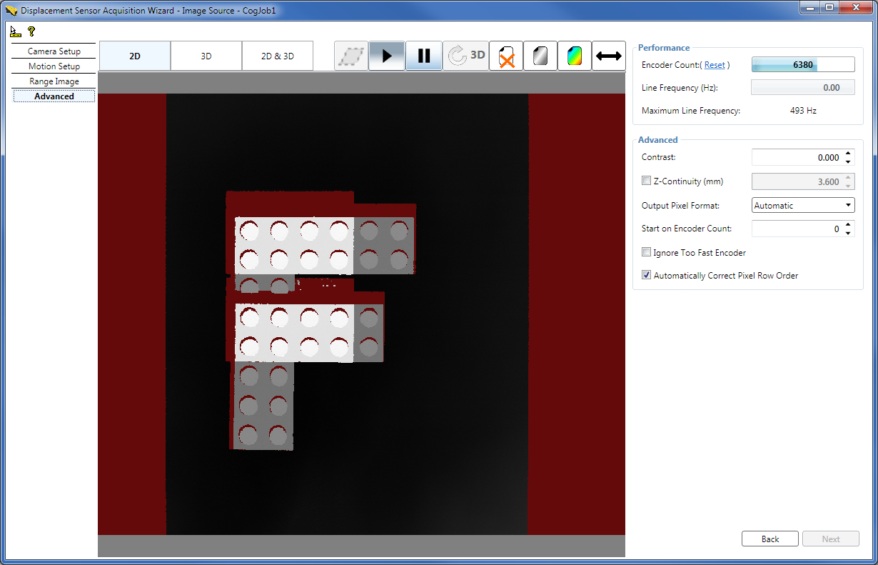
The advanced tab contains advanced acquisition parameters, which you typically do not need to change from the defaults for most acquisition scenarios. These include contrast setting for the GigE camera in the displacement sensor, ZContinuityThreshold defining the maximum height difference for adjacent range image pixels to be connected (and shown), output pixel format, at which encoder count to start acquisition, whether to ignore acquisition errors occurring when the image line triggering is faster than the time needed to acquire and process the line, and whether to automatically adjust the range image row order when the motion direction changes from the default.
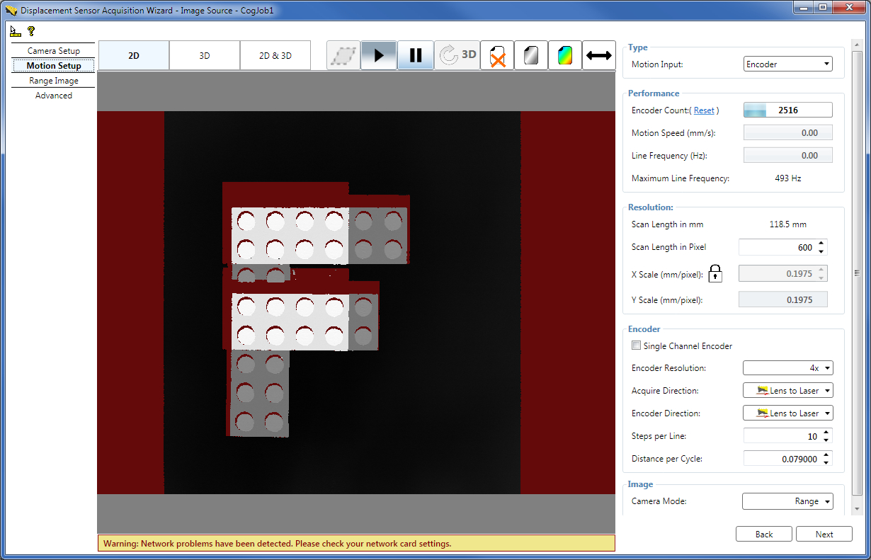
In case the acquisition system detects a problem, the wizard will give you a warning message about it as shown in the following image for a problem related to the network connection between the sensor and the computer.
This section contains steps for quick acquisition setup to help you acquire range images using your displacement sensor in a quick and easy manner. The most typical case is discussed here where the objects to be inspected pass under the sensor in the lens-to-laser direction at a constant known speed (typically, on a conveyor belt), and acquisition is performed using QuickBuild. Once you have set up acquisition and you are successfully acquiring range images, you can refine your acquisition setup based on detailed information on range image acquisition setup and optimization in the Acquiring Images from a DS900 Series Sensor and Acquiring Images from a DS1000 Series Sensor topics.
Caution! While mounting and operating the DS900 and DS1000 series sensors, make sure you know and follow the laser safety instructions for your sensor. These are detailed in the DS900 Quick Reference Guide, DS1000 Quick Reference Guide, and the DS1000 Technical Reference Manual.
Mount your DS900 or DS1000 series sensor so that objects to be inspected pass through its Working Section, which is the portion of the laser plane that the camera in the sensor can see. That is, the Working Section is the cross section of the camera's Field of View and the laser plane. Mount your sensor so that its laser plane is perpendicular to the direction of movement; the laser plane is aligned with the plane defined by the sensor's high-accuracy planar mounting pins. Also, make sure the sensor's optical centerline (the line crossing the centers of its Master Pin and Location Pin while being aligned with the laser plane) is aligned with the direction in which you want to measure height. For detailed mounting information, see the DS900 Quick Reference Guide or the DS1000 Quick Reference Guide.
Set up the displacement sensor wiring, connect it to your computer, and power it on as described in the DS900 Quick Reference Guide or DS1000 Quick Reference Guide.
Configure the connection between your computer and your sensor. The displacement sensor has a GigE camera (which observes objects passing through the Working Section). Once you have connected and applied power to your sensor, configure your sensor in your network as a general GigE camera using the GigE Vision Configuration Tool utility. Choose All Programs->Cognex->VisionPro->Utilities->GigE Vision Configuration Tool from the Start menu to start the tool. Configure the network interface card (NIC) and camera IP addresses. For information on GigE camera configuration, see the GigE Vision Cameras User's Guide, as well as the GigE and CogAcqGigEVisionTransport class topics.
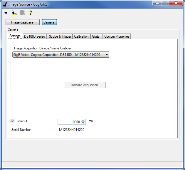
Initialize acquisition in QuickBuild's Image Source window by selecting your displacement sensor as the image source and clicking Initialize Acquisition on the Settings tab.
Launch the Displacement Sensor Acquisition Wizard by clicking the Launch Wizard... button on the DS1000 Series/DS900 Series tab.
Note: By launching the acquisition wizard, the laser will light up unless the LaserMode is set to Off.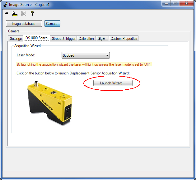
Motion Setup
On the Motion Setup tab, while making sure the Encoderless option is selected (default), enter the speed at which your objects to be inspected will travel under the sensor. Select your desired Y resolution (mm/pixel) by setting YScale. For features in the range image to appear with the same aspect ratio as they appear in the real world, click the lock symbol beside the X Scale field to have it updated automatically to the YScale value. You can also define the Acquire Direction (AcquireDirectionPositive).
Place your object to be inspected on your moving conveyor belt, and watch as the wizard acquires a range image of it as it passes through the Working Section. Click the pause button once you have acquired the range image in order for it to stay on the display for further setup steps. (If you want to acquire another range image, click the resume button and allow your object to pass under the sensor again.)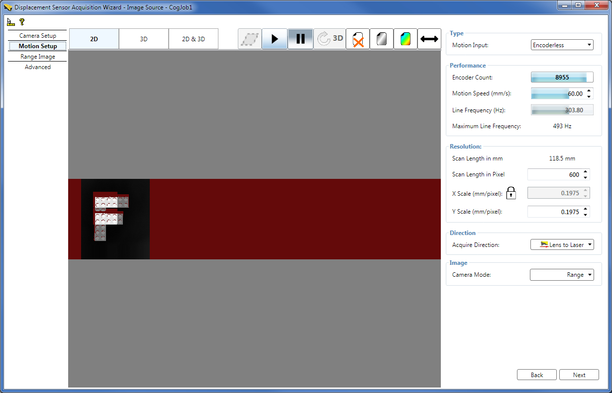
If the Motion Speed you set and the resulting Line Frequency exceed the limit beyond which the sensor is unable to acquire and process each range image line within the available time, defined by the Maximum Line Frequency, and as a result encoder overrun errors occur, the Motion Speed and the Line Frequency fields become reddish and red horizontal lines of missing pixels appear in the range image.
To avoid missed lines, given that the motion speed is a constant property of your system, you can try the following:
- Decrease the range image resolution by increasing the YScale and XScale values for initial range image acquisition.
- Perform the suggested acquisition parameter optimization steps in the section about optimization for speed in the Acquiring Images from a DS900 Series Sensor and Acquiring Images from a DS1000 Series Sensor topics.
Range Image Setup
On the Range Image tab, grab and move the dashed first and last pixel indicator guides so your range image has the appropriate horizontal size. You can observe the effect of these adjustments in the new range image the wizard acquires. (Click the resume button to acquire a new range image if you have paused the acquisition previously.)
On the Motion Setup tab, set the Scan Length, which defines the vertical size of the range images you will acquire from the Job.
Close the Displacement Sensor Acquisition Wizard.
Note: All acquisition parameters will be saved every time you close Acquisition Wizard.
Once you have closed the Displacement Sensor Acquisition Wizard, you can start acquiring range images from the Job.
Note: Simultaneous acquisition from the Job and the wizard is not supported. Doing so may appear to work, but the Job will be unable to reliably acquire images because it is competing with the wizard for access to the camera.
-
Setting up a concrete physical encoder (if you are using one).
Quick setup steps (detailed in the 7. Set Motion-related Parameters on the Motion Setup Tab section):
- On the Motion Setup tab, set the MotionInput to Encoder.
- Adjust encoder settings including DistancePerCycle, Steps per Line, the encoder type (single or dual channel), and EncoderResolution as detailed in the 7. Set Motion-related Parameters on the Motion Setup Tab section.
- Link XScale to YScale to preserve aspect ratio in the output range image.
- Set the Scan Length such that your inspected object will be fully covered by the acquisition, that is, the Scan Length should be greater than the size of the inspected object.
- Setting low-level acquisition parameters to enhance the range image quality, for example, to avoid spurious reflections or over-exposure.
- Optimizing for speed and/or resolution along the X, Y, and Z axes of the Sensor3D coordinate space associated with range images.