This topic contains the following sections.
- VisionPro Shapes and Selected Spaces
- How is a Shape's Selected Space Set?
- Why is a Shape's Selected Space Important?
- A Shape's Selected Space Controls How it Appears in Model Maker
- A Shape's Selected Space Controls Which Pixels are Used for Polarization
- A Shape's Selected Space Controls How Key Tolerance Settings Are Interpreted
- A Shape's Selected Space Affects How Patterns Are Trained
- When are Shapes Mapped Between Spaces?
- What Space Should I Use?
This topic provides an overview of the issues related to coordinate spaces when you use shape training to train a PatMax pattern using shape models.
Before reading this topic you should be familiar with the following information:
- Coordinate spaces, space names, and space trees
- Image calibration
- PatMax shape training
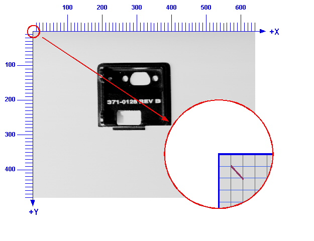
Each VisionPro shape object (and each VisionPro shape model) has a selected space. A shape's selected space is a string that gives the name of the space in which the geometric properties of the shape are defined. For example, a CogLineSegment object has a start point and an end point. A CogLineSegment's selected space determines what coordinate space those points are in. If the points defining a CogLineSegment are (1, 1) and (2, 2) and the selected space of the line is "@", then the line would look like this when displayed with a 640x480 image (the "@" coordinate space is shown in blue):
If the same CogLineSegment's selected space was changed to "inch_space", and it was displayed with an image with a coordinate space tree that included a definition for "inch_space", then the appearance of the line would depend on the definition for that space. If, for example, "inch space" was a calibrated, right-handed space with its origin at the center of the image, then the line might appear like this ("@" space is shown in blue and "inch space" is shown in red):
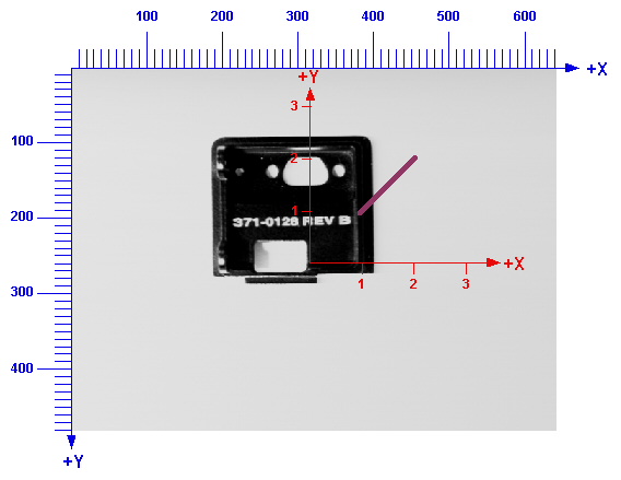
It is important to keep in mind that the geometric properties of the line have not changed between the two pictures. Only the selected space has changed.
Note: You display VisionPro shapes by adding them to a CogDisplay's StaticGraphics or InteractiveGraphics collection. The control renders the shapes by mapping the shapes' geometric properties through the space tree of the image being displayed by the CogDisplay control based on each shape's selected space, exactly as described above.
When a VisionPro shape is created, its selected space is set to "." by default. The "." space means that the shape's geometric properties are interpreted in whatever coordinate space is currently selected for the image. When you extract shapes from an image, import shapes from a CAD file, or draw shapes using Model Maker, the newly created shapes' selected spaces are set as shown in the following table:
| How Shape is Created | Default Selected Space | Notes |
| Programmatically | "." | |
| Shape Extraction CogShapeExtract | Selected space of image used for extraction. | Fully-qualified name is set. |
| Shape Extraction in Model Maker | Space selected in Model Maker's SSN menu. | Fully-qualified name is set. |
| Shape Import CogCADFile | User-supplied space name. | Same name applied to all shapes extracted at a given time. |
| Shape Import in Model Maker | Space selected in Model Maker's SSN menu. | Fully-qualified name is set. |
| Shapes Drawn in Model Maker | Space selected in Model Maker's SSN menu. | Fully-qualified name is set. |
In addition to determining how a shape is rendered for display by a CogDisplay control, a shape's selected space affects several aspects of PatMax shape training.
As described above, whenever a VisionPro shape is displayed, it is rendered based on its geometric properties, the name of its selected space, and the coordinate space tree of the image with which it is being displayed. If you are trying to visually associate an imported or extracted shape with features in an image, then the shape's selected space must correspond to a meaningful space in the image.
When you polarize shapes using image data, both using Model Maker and the shape polarization CogShapePolarize, VisionPro maps the shapes to the pixel coordinates of the supplied image based on the shapes' selected space name and the coordinate space tree of the image.
When you extract, import, and polarize shapes, several of the tolerance parameters that you can supply must be specified in the selected space of the image or shapes. The following table summarizes these parameters:
| Function | Parameter | Notes |
| Shape Extraction | ApproximationTolerance | Defined in the selected space of the image being used. |
| ConnectTolerance | Defined in the selected space of the image being used. | |
| PerimeterLimitMinPerimeterLimitMax | Defined in the selected space of the image being used. | |
| Shape Polarization | MinPolarityPerimeter | Defined in the selected space of the image being used. |
| ProbeResolution | Defined in the selected space of the image being used. (Not available in Model Maker.) | |
| Shape Import | connect tolerance and spline approximation | If you are using the API, these values are specified in the units of the DXF file. If you are using Model Maker, a fixed value of 0.25 is used for the ConnectTolerance and SplineApproximationTolerance values and a fixed value of 1.0 is used for the SplineApproximationSpacing value. These values, however, are interpreted in pixels and then mapped using the selected space before being passed to the CAD File Import package. |
When you train a PatMax pattern using shape models, PatMax uses a transformation to map those shapes to a pixel space before computing the pattern granularity used to train the pattern. If the combination of the shapes' selected space and the training image's coordinate space tree (or the explicit TrainShapeModelsTransform) does not provide shapes with a scale that matches the expected patterns size in the run-time images, the resulting pattern may not produce good search results.
Ordinarily, once a shape has been created, its selected space does not change. If you move or resize the shape, its geometric properties are changed, but in general its space is not changed.
In Model Maker, however, whenever you change the value in the SSN popup, Model Maker performs the following actions:
- It changes the selected space of the image in the Model Maker display.
- It changes the selected space of each shape in the shape collection.
- It asks you if you would like to remap the shapes to the new space.
If you map the shapes to the new space, then the geometric properties of all of the shapes are modified so that their relationship to the pixels in the image is unchanged when the selected shape of the image is changed. If you do not map the shapes to the newly selected space, then the shapes' geometric properties are not changed, so their appearance on the display (their relationship to the pixels in the image) will change.
For example, if Model Maker's display includes a line segment with a start point of (1, 1) and an end point of (2, 2), the currently selected space is "@", and you switch to the "inch_space" described above, if you instruct Model Maker to map the shape, the line's appearance would be unchanged, but its geometric properties would be mapped to the new space. If you instruct Model Maker not to map the shape, then its appearance would change (it would appear much larger), but its geometric properties would stay the same.
In almost all cases, you are using VisionPro to work with images of objects in the physical world. For best results, you should use a consistent, calibrated coordinate space with units and handedness that correspond to the physical environment. For example, if you are using VisionPro to locate features in aerial photographs, and you have geographic positioning system (GPS) data expressed in kilometers, you should create a calibrated space that relates image pixels to kilometers. If you are working with microscopic images and you have CAD data expressed in microns, you should create a calibrated space that relates image pixels to microns.