This topic contains the following sections.
VisionPro's CAD File Import Package lets you convert the shapes contained in a DXF-format CAD file into a collection of VisionPro shapes or shape models. As shown in the following figure, you can convert all of the shapes in a file or only the shapes within a DXF layer or group:
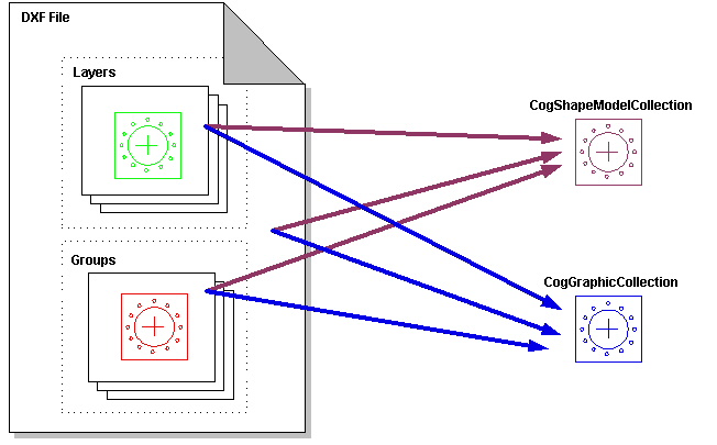
If you are importing shapes from a CAD file to create a shape-trained PatMax pattern, you should import the shapes as a CogShapeModelCollection.
This section provides an overview of the DXF file format and describes how VisionPro imports the shape information from DXF files and converts it into VisionPro shapes or shape models.
The DXF format is an evolving standard, closely tracking released versions of AutoCAD software. VisionPro supports text-based DXF files in formats corresponding to the versions of AutoCAD shown below. VisionPro does not support the binary version of the DXF file format.
| DXF Version ID | AutoCAD Version | Notes |
| AC1009 | R11 | Same DXF version as R12 |
| AC1009 | R12 | Supported by VisionPro |
| AC1012 | R13 | Supported by VisionPro |
| AC1014 | R14 | Supported by VisionPro |
| AC1015 | 2000 | Supported by VisionPro |
| AC1015 | 2000i | Same DXF version as 2000 |
| AC1015 | 2002 | Same DXF version as 2000 |
The DXF file format is divided into sections. The following table shows the DXF section names and how they are parsed by VisionPro during CAD file import.
| DXF Section | Import Action |
| HEADER | Ignored |
| TABLES | Parsed for information about the drawing’s layers |
| BLOCKS | Parsed for information about any custom objects and groups |
| ENTITIES | Parsed for information about basic drawing shapes and primitives |
| CLASSES | Ignored |
| OBJECTS | Parsed for group information |
The DXF ENTITIES section contains one or more entities, each of which correspond to CAD drawing primitive shapes. The following table shows how the DXF entities are mapped to VisionPro shapes.
| DXF Entity | VisionPro Shape |
| ARC | CogEllipticalArc |
| CIRCLE | CogEllipse |
ELLIPSE | Depending on the angle span of the DXF file's ELLIPSE entity, the imported shape may be represented as a single CogEllipticalArc or as a CogGeneralContour object with two elliptical arc segments. |
| INSERT | CogGeneralContour |
| LINE | CogLineSegment |
| LWPOLYLINE | CogGeneralContour |
| MLINE | CogGeneralContour |
POINT | Keep in mind that there is no shape model object that corresponds to a CogPointMarker. Model Maker will ignore any POINT entities in a DXF file; if you want to import POINT entities, you must use the GetShapes method. |
| POLYLINE | CogGeneralContour |
| RAY | CogLine |
| SOLID | Boundary converted to CogGeneralContour |
| SPLINE | Approximated by a CogGeneralContour |
| XLINE | CogLine |
The following DXF entities are ignored by VisionPro during import.
3DFACE, HATCH, SEQEND, 3DSOLID, IMAGE, SHAPE, ACAD_PROXY_ENTITY,
LEADER, TEXT, ATTDEF, MTEXT, TOLERANCE, ATTRIB, OLEFRAME, TRACE,
BODY, OLE2FRAME, VERTEX, DIMENSION, REGION,VIEWPORT
You import shapes from a DXF file using the properties and methods defined in the CogCADFile interface. The interface's methods offer you some control over how shapes are imported.
In all cases, however, the imported shapes are returned to you as either a CogShapeModelCollection (if you request shape models) or a CogGraphicCollection if you request shapes) that contains the individual shapes. The imported shapes will always include CogGeneralContour objects and primitive shape objects such as CogLineSegments.
Most CAD files contain thousands of discrete, unconnected shape entities. In most cases, PatMax shape training will work better if related discrete shapes are connected into larger VisionPro shapes. For example, if the CAD file represents a rectangular shape using four contiguous LINE entities, PatMax will be more effective if those shapes are converted into a single CogPolygon.
You enable or disable the connection of shapes using the ConnectEnabled property. If shape connection is enabled, only the endpoints of adjacent shapes are connected. You specify the distance, in the DXF file's coordinate space units, within which two shapes' endpoints must lie of each other to be connected using the ConnectTolerance property.
As you increase the value of the ConnectTolerance, the imported CogShapeModelCollection will tend to have fewer, larger CogGeneralContour objects and fewer shape primitives. If you specify a value of 0 for the ConnectTolerance , the imported shape collection will still include some CogGeneralContour objects.
Often, DXF files may use many (tens of thousands) of very small graphic entities to represent complex shapes. Even when mapped through an appropriate calibrated coordinate space, the size of these shapes may be much less than a pixel, or even a tenth of a pixel. If you specify a connect tolerance of 0.25, and the DXF file contains a number of shapes each 0.05 pixels in size and lying within 0.25 pixels of each other, VisionPro may connect the shapes in inappropriate ways that produce degenerate shape errors (such as line segments which have the same start and end point).
If your DXF files contain large numbers of tiny shapes, you can prevent degenerate shape connection errors by specifying an appropriately small connect tolerance. If possible, however, you should attempt to modify the way in which the DXF file is created to reduce the number of shapes in the file.
Note: The Model Maker control does not let you specify the connect tolerance value explicitly. Instead, it lets you choose between not connecting shapes, connecting shapes that touch (using a fixed value for ConnectTolerance of 0.000000001), or connecting shapes that are nearby (using a fixed value for ConnectTolerance of 0.25 pixels, mapped through the selected selected space that you have selected in Model Maker's SSN popup menu). If you experience degenerate shape errors on import using Model Maker, specify Connect Coincident Points for the shape connection method.
VisionPro does not include a spline shape. When you import SPLINE entities from a DXF file, VisionPro converts these shapes into CogGeneralContour shapes. Because CogGeneralContour shapes comprise line segments and elliptical arc segments only, many spines can only be approximated rather than duplicated using a CogGeneralContour shape. The accuracy with which the spline is modeled depends on the number of segments in the CogGeneralContour. You control this value by specifying the maximum fit error (SplineApproximationTolerance) and the spacing at which to measure the fit error (SplineApproximationSpacing). You specify these values in the DXF file's coordinate space units.
Note: The Model Maker control does not let you specify these values. Instead, it uses a fixed value of 0.25 pixels for SplineApproximationTolerance and a fixed value of 1.0 pixels for SplineApproximationSpacing. Also, it maps these values to pixels using the selected space that you have selected in Model Maker's SSN popup menu.
CAD drawings are usually constructed in layers. For example, one drawing layer might contain the lines and arcs of the drawing itself, while another layer contains text annotations. You can specify which drawing layer or layers to import using the VisionPro CAD file import package. You can determine the layers that are present in a DXF file in several ways.
- Model Maker displays the layers when you import a DXF file.
- You can use the GetLayers function.
- You can view the DXF file in AutoCAD's free viewer Volo View Express, which is available for download from AutoCAD.
AutoCAD software also supports a feature called groups that allows the user to create a named group of objects that have a feature in common, independent of their hierarchy in the drawing. For example, all of the components of an assembly drawing that are sourced from the same vendor might be placed in the same group. Grouped objects can be on any drawing layer, and can thus cross layer boundaries.
You can use the same techniques you use to enumerate DXF layers to enumerate DXF groups.