This topic contains the following sections.
- Understanding High-Pass Filtering of Range Images
- When to Use High-Pass Filtering
- How to Configure High-Pass Filtering
- Filtered Range Image Pixel Values and Coordinate Spaces
When you acquire a range image of a part with a curved or varying-height surface, and the features of interest on the part are small, the height information about the small features can be difficult to locate and detect, because it is overshadowed by the larger height changes across the overall part surface. The following range image illustrates the appearance of such a part in a range image:
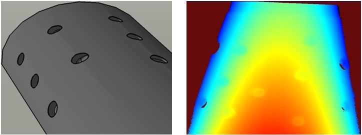
High-pass filtering allows you to remove low-frequency information, such as part curvature or surface undulations, while preserving high-frequency features such as small bumps or voids.
High-pass filtering works by applying a mean or median smoothing filter to the input image, then subtracting the resulting smoothed image from the input image.
The following image shows the appearance of a range image of a part with a curved surface along with a profile view of the indicated section of the range image. The large color gradient reflects the overall shape of the part surface. Note that the pixel values for the individual voids vary significantly from void to void:
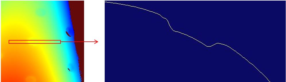
After high-pass filtering, the overall part surface height is more uniform, and the indicated heights of the individual voids are the same.

High-pass filtering of range images may be useful or essential in several cases:
If you are using a 3D analysis tool that makes use of a reference plane, such as the Height Calculator tool or the Volume Calculator tool, an undulating, curved, or tilted surface can make it difficult to specify an accurate and repeatable reference plane.
Pre-processing the image with a high-pass filter can allow accurate, repeatable placement of the reference plane.
If you are using an 8-bit vision tool such as the Caliper tool to measure or locate small features that are at different heights, it may not be possible to create an 8-bit greyscale image that provides sufficient contrast across features at different heights.
Pre-processing the image with a high-pass filter can allow you to generate a single 8-bit greyscale image that has sufficient contrast to be used with these types of 8-bit tools.
If you are using the Blob tool to analyze the size and shape of features on a curved surface, it may not be possible to select a single segmentation threshold value that will segment features at different heights from a background of varying height.
Pre-processing the image with a high-pass filter will allow youto select such a threshold.
High-pass filtering is usually not required if you are using a 2D vision tool that natively supports range images. Both the PMAlign and OCRMax can be used on undulating, curved, and tilted surfaces without any preprocessing.
To apply a high-pass filter to a range image, create an CogIPOneImageTool and add a High-Pass Filter operator.
| The Gaussian processing mode is not supported for range images; you must select Median or Mean. |
For most applications, the Median processing mode provides the most accurate results. When specifying the kernel size, in most cases you should specify a square kernel that has a total area greater than two times the area of the features you wish to preserve, in pixels.
For example, in the example images shown above, the voids are roughly circular in shape with a diameter of 30 pixels, giving an area of approximately 700 pixels. An appropriate kernel size would be 40x40 pixels (1,600 pixels, slightly more than twice the feature size).
| The kernel sizes typically used with range images are larger than those used for non-range images. This is because when processing a range image, it is important to preserve the entire area of the feature, not just the feature's edges. |
When the high-pass filter is applied to an input range image, it creates a new output range image that reflects the result of applying the specified kernel. The pixel values in the output range image are normalized so that a pixel value of 32,768 corresponds to the mean or median (depending on the processing mode) value of the pixels in the input image used to compute that pixel in the output image.
Pixel values greater than 32,768 represent heights that are above the median (or mean) height, and pixel values less than 32,768 represent heights that are below the median (or mean) height.
Because of this normalization operation, there is no longer a linear relationship between pixel values and physical heights in the original image's Sensor3D space. The relationship between image feature positions in the X- and Y-direction, however, are exactly the same in the output range image as they were in the input range image.
The high-pass filter operator creates a single new 3D coordinate space in the output range image's 3D coordinate space tree. This space is named Sensor3D_HP. For the X- and Y-coordinates, the new space is identical to the input image's Sensor3D space. The Z-axis of the new space is parallel to the Z-axis of the input image's Sensor3D space, but the Z-origin is set to correspond to a range image pixel value of 32768.
The 3D positions that correspond to pixel values below 32768 will have negative Z-values in Sensor3D_HP space, while the 3D positions that correspond to pixel values above 32768 will have positive Z-values in Sensor3D_HP space.
If the input range image's 3D coordinate space tree includes additional 3D spaces that you have defined, those spaces will be treated as follows:
|