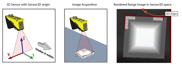
As your Cognex 3D displacement sensor generates height-profile information about three-dimensional objects that pass within the field of view, VisionPro renders the resulting range image in a 3D coordinate space. By default, VisionPro renders range images in the Sensor3D coordinate space: a calibrated 3D space with an origin fixed relative to the sensor and whose positive y-axis is perpendicular to the laser, as shown in the following figure:
If your DS sensor uses a calibration data file generated by performing a field calibration, your application has additional 3D spaces from which you can choose to render the corrected range image:
- YLockedToMotion: A calibrated coordinate space with a Y-axis of the corrected image aligned with the vector of motion
- Phys3D: A world coordinate system that can be shared between multiple 3D sensors that are calibrated together, whose origin is relative to the calibration target
- Sensor[x]_Sensor3D: The Sensor3D space relative to 3D sensor [x] when you field calibrate a collection of 3D sensors
The 3D coordinate space you choose to rerender your range images can depend largely on the needs of your application. Rendering a range image in YLockedToMotion space can, for example, introduce more missing pixels than the same vision data rendered in Sensor3D space.
In some vision applications, you might want to generate an entirely new coordinate space and use it to rerender an existing range image before you analyze it with additional 2D and 3D vision tools. For example, your production environment might constrain how you mount the 3D sensor above the motion plane and force your application to generate range images as shown in the following figure:
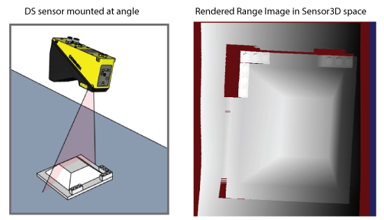
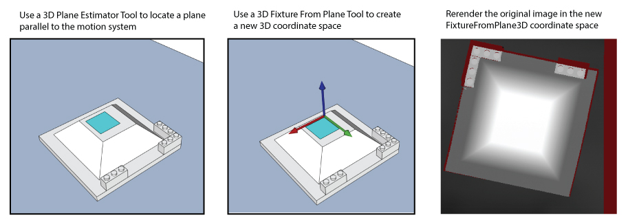
3D tools such as 3D Height Calculator tool and 3D Volume Calculation tool generate more accurate results when the sensor is oriented perpendicular to the object, so your application might employ a strategy similar to the following in order to rerender the range image :
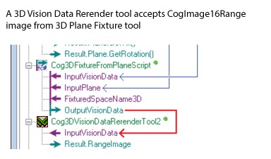
Use a Cog3DVisionDataRerender tool to rerender a range image in a different coordinate space of the 3D coordinate space tree. Rerendering a range image can improve the effectiveness of other vision tools that later analyze the rerendered image. A Cog3DVisionDataRerender tool can accept a CogImage16Range height-profile range image from any image source in your application:
Be aware, however, that the tool cannot create new image data. Features that were not visible to the 3D sensor in the original range image will never become visible after a rerendering. In addition, features from the original range image can be lost depending on the orientation of the new 3D coordinate space you use.
If your application performs 3D alignment, the 3D Align tool creates a new pose representing a found pattern in three-dimensional space. Use a 3D Fixture Script ToolBlock to generate a 3D fixtured coordinate space based on the found pose and use a Cog3DVisionDataRerender tool to generate a new range image based on this coordinate space.
This topic contains the following sections.
As you configure a Cog3DVisionDataRerender tool you must choose the OutputSpaceName3D coordinate space to rerender the data from the original range image. The input range image you want to rerender must contain this 3D coordinate space in its Cog3DCoordinateSpaceTree.
Tools such as the 3D Fixture Script ToolBlock accept an input range image, generate a new 3D coordinate space, and attach it to an output range image for use by a Cog3DVisionDataRerender tool. As an alternative, your application can generate a custom 3D coordinate space and use the AddSpace API to attach it to the Cog3DCoordinateSpaceTree of an existing range image before passing it on for rerendering.
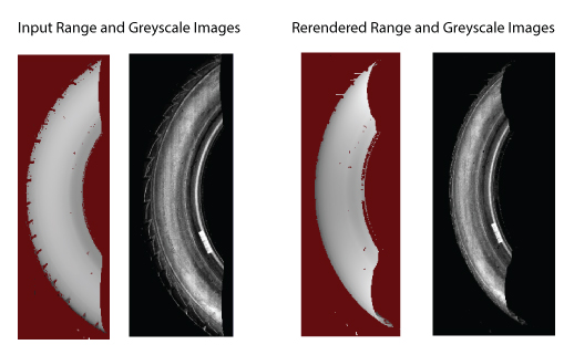
In addition to capturing height-profile information, your Cognex 3D sensor can also capture 3D RangeWithGrey images that contain additional 16-bit greyscale data. When you supply a 3D RangeWithGrey image to a Cog3DVisionDataRerender tool, it can generate any of the following:
- A rerendered CogImage16Range range image
- A rerendered CogImage16Grey greyscale image
- Both a rerendered CogImage16Range range image and a rerendered CogImage16Grey greyscale image, as shown:
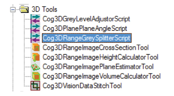
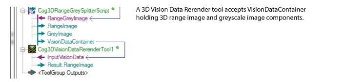
To produce both a rerendered range image and/or a rerendered greyscale image you must first use a Cog3DRangeGreySplitterScript CogToolBlock to split the image into its 3D range image and grey image components before giving it to the Cog3DVisionDataRerender tool. Locate the Cog3DRangeGreySplitterScript CogToolBlock under 3D Tools in the QuickBuild tool palette:
The toolblock generates a CogVisionDataContainer that can be used as input to a Cog3DVisionDataRerender tool.
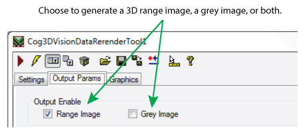
When combined with the correct Output Enable setting on the Cog3DVisionDataRerender edit control or the OutputEnable property of the VisionPro API, the tool will generate a rerendered range image and greyscale image.
See Image Stitching for more details on using the CogVisionDataContainer class. See the topic Working with 3D RangeWithGrey Images for more information about working with RangeWithGrey images.
If your application performs 3D alignment, the 3D alignment tool creates a new pose representing a found pattern in three-dimensional space. Use a 3D Fixture Script ToolBlock to generate a fixtured coordinate space based on the found pose and use a Cog3DVisionDataRerender tool to generate a new range image based on this coordinate space.
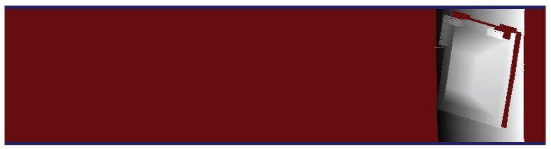
By default, a Cog3DVisionDataRerender tool uses the height properties of the input range image to generate a rerendered range image of maximum size in the X-Y coordinate system. For many vision applications this can generate range images with a large number of missing pixels:
Just as many 2D vision tools support a rectangular region of interest, the Cog3DVisionDataRerender tool allows you to limit the X-Y coordinate system of the rerendered range image.
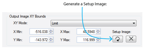
Use the Cog3DVisionDataRerender edit control or the OutputImageXYMode API to change from the default Auto mode to Limit mode. The edit control allows you to use an interactive graphic to set the X-Y bounds of the rerendered range image with the following steps:
- Switch the Output Image XY Bounds option XY Mode from Auto to Limit.
Click the button to generate a Setup Image, a maximum-sized range image in the X-Y coordinate system:
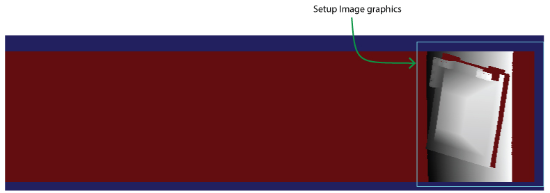
- Switch to the Current.SetupImage in the image buffer:
Use the graphics in the Current.SetupImage to surround the portion of the Setup Image containing the rerendered image data:
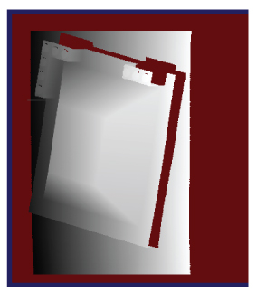
Run the tool again and examine the LastRun.OutputRangeImage to verify the generated 3D range image contains fewer missing pixels.
The dimensions of any graphics you use to specify the portion of the Setup Image to use as the border of the output range image are reflected in Min and Max parameters of the edit control:
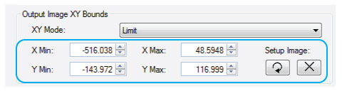
You can specify exact values for any of these parameters as your application requires.
A Cog3DVisionDataRerender tool supports additional parameters that affect the rerendered 3D range image.
Adjacent pixels in the 3D range image data can have varying height values. If neighboring pixels have a height value greater than a set Z Continuity Threshold parameter, the tool renders the pixels disconnected and not part of the same continuous surface. A discontinuity can affect the results of other 3D tools that analyze the output range image.
By default, this parameter is not enabled.
By default the Cog3DVisionDataRerender tool creates an output 3D range image at the same scale as the input image, but you can choose to specify a different scale along each of the X, Y, Z axes. For example, your application might benefit from a smaller, lower-resolution image that rescaling the output image can generate.
By default, a Cog3DVisionDataRerender tool makes no assumptions of the range of Z values and sets Z = 0 as the minimum output height value in the rerendered 3D range image.
If you have prior knowledge of the range of pixels values in your rerendered 3D range image, you can choose to enable the OutputImageZMin parameter and set a value closer to the expected minimum height based on your production environment. This can result in a better utilization of the available 16 bits of dynamic range in the rerendered height data.
By default, a Cog3DVisionDataRerender tool uses Auto mode, making no assumptions of the range of Z values and setting Z = 0 as the minimum output height value.