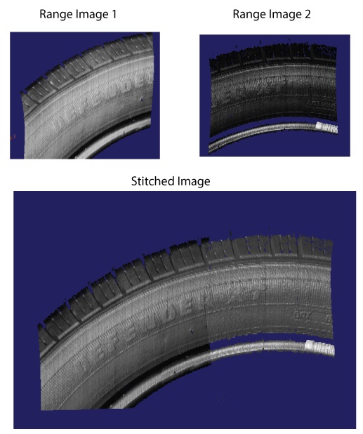
Some vision applications require that two or more 3D sensors capture a single field of view and combine the images for analysis by other 3D and 2D vision tools. To combine two or more simultaneous scans, VisionPro must perform image stitching, a process that combines a set of individual 3D range images into a single, merged range image. Use a Cog3DVisionDataStitch tool to perform image stitching. For example, the following image shows two 3D range images and the stitched image the Cog3DVisionDataStitch tool can generate:
Successful image stitching requires that the field of view for all participating sensors be field calibrated so that they share a unified 3D coordinate space. See the topic Field Calibration for more information on field calibration. Although VisionPro does not prohibit the use of the Cog3DVisonDataStitch tool with 3D range images that are not field calibrated, the results will generally be unreliable for later analysis by 3D and 2D vision tools.
The Cog3DVisonDataStitch tool allows you to stitch 3D range images containing only height-profile information and 3D RangeWithGrey images that contain both height-profile information and 16-bit greyscale data. See the topic Working with 3D RangeWithGrey Images for more information on RangeWithGrey images.
Be aware the Cog3DVisonDataStitch tool does not support image stitching with a mix of 3D range images and 3D RangeWithGrey images.
See the following sections for more information:
Unlike many 3D vision tools that accept a CogImage16Range object, the Cog3DVisonDataStitch tool takes a single CogVisionDataContainer as an input. A CogVisionDataContainer is an indexed list of key/value pairs. For each pair:
- The key is a string that you define to name the source of the incoming image data.
- The value is a reference to a type ICogVisionData that will store 3D range image data.
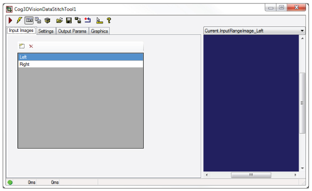
As you configure a Cog3DVisonDataStitch tool you define the elements of the CogVisionDataContainer. For example, the following figure shows a Cog3DVisonDataStitch edit control with two entries to indicate this tool will combine the incoming images from two 3D sensors that you designate with names Left and Right:
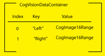
Without 3D range image data, the CogVisionDataContainer for this Cog3DVisonDataStitch tool can be represented as shown in the following graphic:
As you continue to configure the tool the contents of the CogVisionDataContainer are modified.
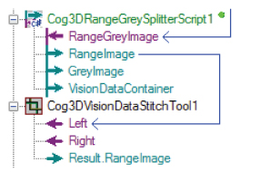
In QuickBuild, you can link 3D range images directly to their corresponding keys in a Cog3DVisionDataStitch tool. The following figure shows a Cog3DVisonDataStitch tool with two input 3D range images:
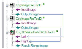
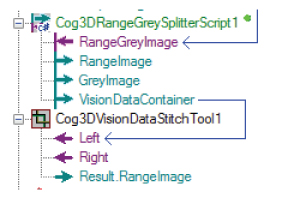
The 3D range images become Value links in the CogVisionDataContainer for this Cog3DVisionDataStitch tool, as shown in the following graphical representation:
Your Cognex 3D sensor can capture 3D RangeWithGrey images that contain both height-profile information and 16-bit greyscale data, but a Cog3DVisionDataStitch tool cannot accept a 3D RangeWithGrey image directly. You must use a Cog3DRangeSplitterScript CogToolBlock to split the image into its 3D range image and grey image components.
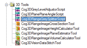
Locate the Cog3DRangeSplitterScript CogToolBlock under 3D Tools in the QuickBuild tool palette:
The Cog3DRangeSplitterScript CogToolBlock generates three outputs:
- A 3D range image
- A 16-bit greyscale image
- A CogVisionDataContainer that itself contains both the 3D range image and the 16-greyscale data.
Many vision applications use the output from a Cog3DRangeSplitterScript CogToolBlock to analyze the separate 3D range image and greyscale images using 3D and 2D vision tools, respectively. If you are splitting the RangeWithGrey image for use with a Cog3DVisionDataStitch tool, you have two options:
Use the 3D range image from the Cog3DRangeSplitterScript CogToolBlock:
Take the 3D range image when you want to generate a stitched image with height-profile information only.
Use the CogVisionDataContainer object from the Cog3DRangeSplitterScript CogToolBlock.
Taking the CogVisionDataContainer object allows the stitched image to contain both the height-profile information and the greyscale data from the original RangeWithGrey range image.
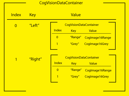
Whether you choose the 3D range image or the CogVisionDataContainer, you cannot mix both types of inputs to a Cog3DVisionDataStitch tool. All inputs to a Cog3DVisionDataStitch tool must be either 3D range images or CogVisionDataContainer objects. You can nest any number of CogVisionDataContainers in the single CogVisionDataContainer input to the tool. The following graphic represents a CogVisionDataContainer input with two nested CogVisionDataContainers:
The Cog3DVisionDataStitch tool must render the stitched image in a single output space shared by all the input images. See the topic DS1000 Acquisition Using Field Calibration for more information on range image coordinate spaces.
The tool uses two parameters to know which output space to render the stitched image:
- Output Space Source: The string in the CogVisionDataContainer of the associated 3D range image that contains the unified 3D coordinate space you want to use to render the stitched image.By default, the tool uses the first entry in the CogVisionDataContainer.
Output Space Name 3D: The name of the 3D coordinate space you want to use to render the stitched image.
By default, the tool uses the currently selected space of the Output Space Source. Your choices for the 3D space include:- Phys3D: A common 3D coordinate space for all DS sensors
- Sensor3D: The 3D coordinate space attached to the sensor
- YLockedToMotion: A 3D coordinate space that has the same origin as Sensor3D, but whose Y-axis is parallel to the motion observed during field calibration. The Z-axis direction is as close as possible to the Z-axis of Sensor3D.
Your choice should reflect the 3D space you find suitable for analyzing the stitched image with 3D and 2D vision tools, based on any factor such as the orientation and position of the 3D sensors or the unit of measurement for that coordinate space. For example, choosing YLockedToMotion as the Output Space can correct for any skew in the position of the 3D sensors above the motion plane.
When two input 3D range images overlap, the Cog3DVisionDataStitch tool offers you the following options for choosing output pixel values for any particular destination pixel location:
- MaxZ: Any and all overlapping source pixels whose height is within a given consistency distance along the z-axis of the maximum observed height at that location are averaged to produce the output height value.
- MinZ: Any and all overlapping source pixels whose height is within a given consistency distance along the z-axis of the minimum observed height at that location are averaged to produce the output height value.
- NearestImageCenter: The source pixel height from the input image whose geometric center is closest is chosen, where closest means that the smallest sum of the number of rows and the number of columns from this destination pixel to the geometric center of source image.
- Priority: Assign a priority to the source images and choose the pixel value from the image wih the lowest numerical value (which indicates its higher priority).
The Cog3DVisionDataStitch tool allows you to specify how to scale the stitched range image with two options:
- UseXYZScales: Always use defined X, Y, Z scale values to generate the output range image.
- UseInputImageScales: If all input range images have identical X scale values, and they all have identical Y scale values, and they all have identical Z scale values, then use those same scale values in the output range image.
You can define how the Cog3DVisionDataStitch tool defines the X, Y bounds of the output image with two options:
- Limit: Clip the output in X and Y according to given values for the boundaries in the direction of each.
- Auto: Automatically size the output range image in X and Y to contain the bounding corners (at image Z = 0 and at image Z = 64K) of the input images.
The tool provides two parameters
Z mode: Defines how to handle the Z values of the output range image.
You can choose to let the tool automatically compute the value from the mapping image Z = 0 corner points into output space and taking the miniumum mapped Z value, or specifying a specific value.
- Z continuity threshold: A Z difference threshold such that adjacencies which differ in Z by more than this threshold are disconnected.
For many vision applications, the default values for a Cog3DVisionDataStitch tool produce desirable results when all the 3D range images are acquired from acquisition sources using a shared calibration file. In addition, the speed of the Cog3DVisionDataStitch tool is fastest when all acquisition sources use the same primary sensor and primary 3D space, as defined in the Calibration tab of the Image Source window. Which 3D sensor to choose as the primary sensor and which 3D space to choose as primary space depend on your application.
The Cog3DVisionDataStitch edit control allows you to launch the 3D Viewer to view the rendered output image:
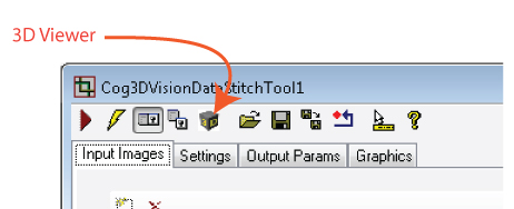
See the topic Viewing 3D Range Images with the 3D Viewer for more information on the 3D Viewer.
Cognex recommends you use Cognex Designer to create your 3D application to analyze stitched images. Contact your Cognex sales representative for more information on Cognex Designer.
For a Designer sample application that performs image stitching, see www.cognex.com/CognexDesignerSamples.