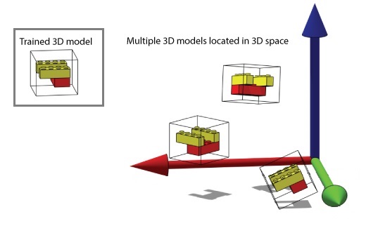
VisionPro contains a set of vision tools that can be combined to create a 3D alignment application for locating the position and orientation of 3D shapes in successive 3D range images. Once your application has a trained 3D model, one or more results can be found within a volume of space:
This topic contains the following sections.
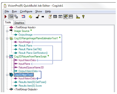
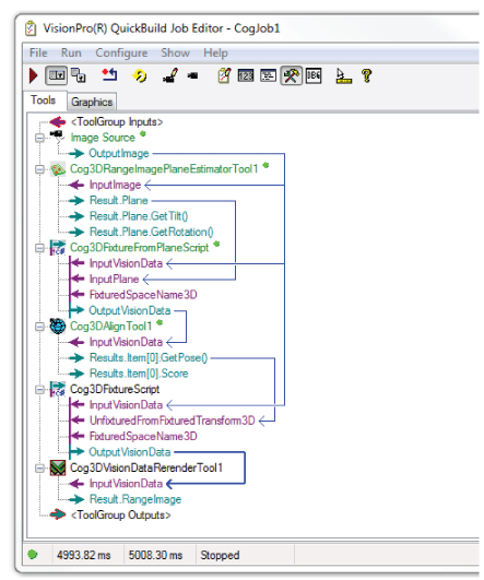
While you use a 3D Align tool to create and search for a trained 3D model, a 3D alignment application requires additional tools to generate useful 3D coordinate spaces and rerender the original 3D range image based on the pose of a found result. A typical 3D alignment application uses a collection of the following tools:
A field calibrated image source from one or more Cognex 3D displacement sensors.
See the topic About this Release for a list of the 3D displacement sensors supported in this release.
- A Cog3DRangeImagePlaneEstimatorTool to identify a base plane where the objects you want your application to analyze can be found.
A Cog3DFixtureFromPlaneScript CogToolBlock to create a 3D coordinate space aligned with the base plane found by the Cog3DRangeImagePlaneEstimatorTool.
This new 3D coordinate space allows you to easily specify 3D regions of space that are aligned with the base plane.
The Cog3DFixtureFromPlaneScript CogToolBlock requires no additional configuration after you add it to your application.
- A Cog3DAlignTool to define a 3D model, the volume of the 3D range image where you want to search for that 3D model, and other run parameters that define how your 3D models might be rotated about the X, Y and Z axes in successive runtime images.
If your application requires you to analyze a 3D range image based on the pose of a found 3D model, your 3D alignment application can also include the following tools:
A Cog3DFixtureScript CogToolBlock to create a new 3D coordinate system based on the pose of a found 3D model and add it to your original 3D range image.
The Cog3DFixtureScript CogToolBlock requires no additional configuration after you add it to your application.
A Cog3DVisionDataRerenderTool to rerender the orignal 3D range image in the 3D coordinate space represented by the orientation of a found 3D model.
3D tools such as 3D Height Calculation tool and 3D Volume Calculation tool might generate more accurate results after the image has been rerendered in the new 3D coordinate space.
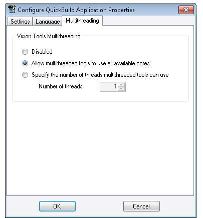
Cognex recommends you enable multithreading for 3D alignment applications. In QuickBuild, choose Configure->QuickBuild Application Properties and enable multithreading as shown:
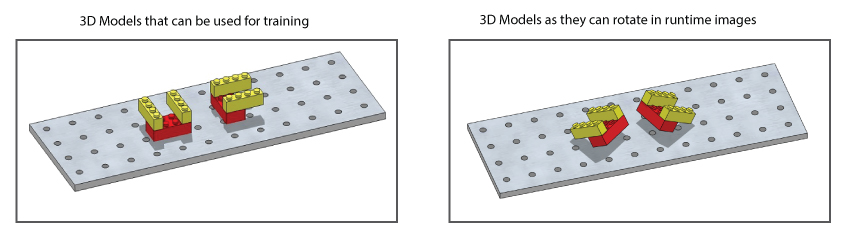
The following procedure describes one method of creating a 3D alignment application using a LEGO model that can change its orientation as shown in the following figure:
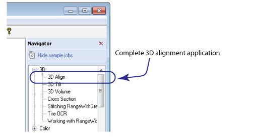
The complete application exists as a QuickBuild sample job as part of your VisionPro installation. Find the job in the Navigator pane under the 3D category:
Perform the following steps to create this application as a guide to creating your own:
Create a new Job in QuickBuild and configure the Image Source to use the image-database file %VPRO_ROOT%\Images\3DAlignLego.cdb.
The image-database file contains two 3D range images. One is for suitable for creating a 3D model and the second can be used for locating that model in a sample runtime image:
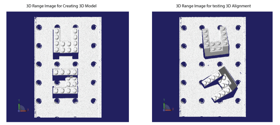
Use the first 3D range image for developing this application.
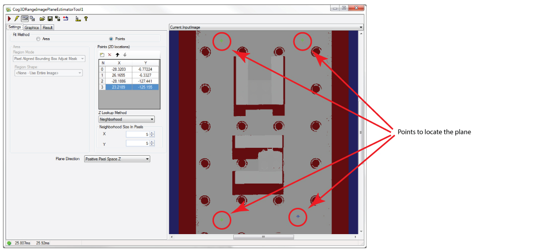
Add a Cog3DRangeImagePlaneEstimatorTool, link the Image Source to the InputImage of the tool, and use it to locate the plane representing the surface on which the LEGO models rest .
Refer to Estimating a 3D Plane for details on using a Cog3DRangeImagePlaneEstimatorTool. For this application, the tool uses four 2D points to identify the surface. Position the 2D location of the points as shown:
Run the Job so that the Cog3DRangeImagePlaneEstimatorTool has a plane to pass onto the next tool.
Add a Cog3DFixtureFromPlaneScript CogToolBlock and give it the Image Source from the image-database file and the plane found by the Cog3DRangeImagePlaneEstimatorTool, as shown:
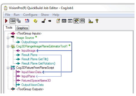
The CogToolBlock contains a script that creates a new 3D coordinate system based on the plane of the surface and makes it the current SelectedSpaceName3D.
Run the Job again and the CogToolBlock generates OutputVisionData you can pass to a 3D Align tool.
Add a Cog3DAlignTool and pass it the OutputVisionData from the Cog3DFixtureFromPlaneScript CogToolBlock:
Run the Job to give the Cog3DAlignTool the 3D range image from the Cog3DFixtureFromPlaneScript CogToolBlock.
Open the Cog3DAlignTool edit control and confirm that the tool uses the first image from the image-database file:
Use the Cog3DAlignTool to define a 3D model as well the volume of space in each 3D range image where you want to search.
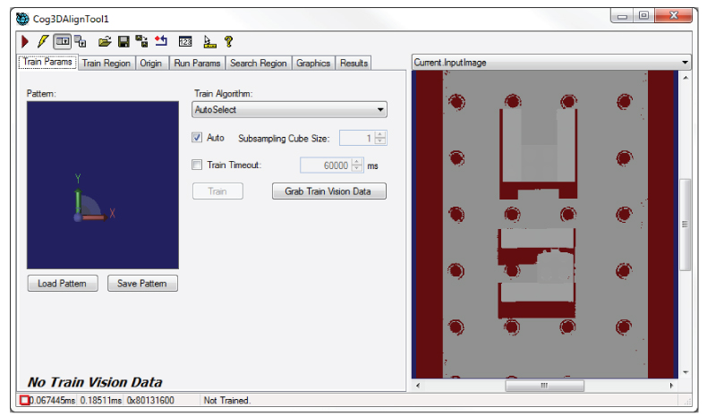
Perform the following steps to create a 3D model from one of the LEGO models:
- Click Grab Train Vision Data on the Train Params tab.
Select the Train Region tab.
The Train Region tab contains a user interface for creating the 3D model you want to search for in successive 3D range images, including a 3D display containing the 3D range image and a 3D graphic representing the current train region:
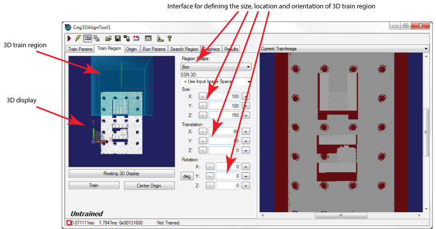
The 3D Display reflects any changes you make to the Size, Translation and Rotation parameters of the train region. The tab also contains a Floating 3D Display button to open a floating 3D display containing the 3D range image and the train region, which can make it easier to see the changes you make to the dimensions of the train region.
Use the Size and Translation parameters to change the dimensions of the train region to surround one of the LEGO models, as shown in the following example:
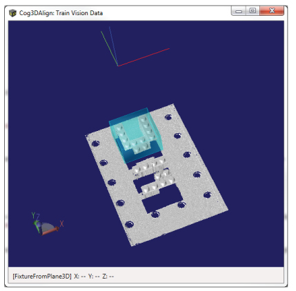
Note: Do not intersect the train region with the base plane whenever possible. A 3D model that includes features from the base plane will have a negative impact on the performance of the 3D Align tool.
- Click Center Origin to center the origin of the model in the middle of the train region.
Click Train to create a trained 3D model. It can take several minutes to train the 3D model. The Cog3DAlignTool edit control will display a notice when the model has been trained:
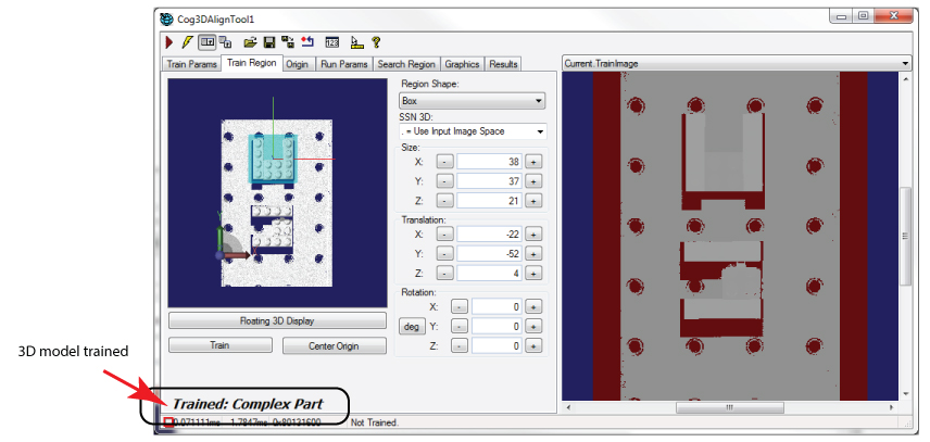
The Cog3DAlignTool edit control also indicates which train algorithm was used to created the trained model.
Click on the Search Region tab:
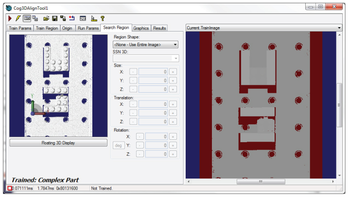
The Search Region tab allows you to define the volume of 3D space where you want to search for the trained search model. By default, the Cog3DAlignTool will search for the trained model in the entire 3D range image, but specifying a smaller search volume will allow the tool to execute faster.
Select the Region Shape and choose Box.
Similar to the Train Region tab, the Search Region tab displays an interface for defining the volume of the search region:
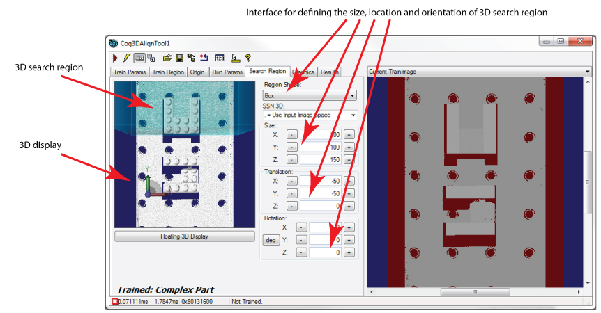
Use the Size, Translation and Rotation parameters to specify a search region that tightly surrounds the volume of space where the 3D models might be found. Launch a floating 3D display to help you set the best parameters for your application. In the following image, the tool uses a search volume large enough to find both 3D models:
Similar to creating the 3D model, avoid defining a search volume that intersects the base plane to improve the performance of the 3D Align tool.
Select the Run Params tab to set parameters that indicate how the trained 3D model can rotate along the (X, Y, Z) axes of a 3D coordinate system, as well as other parameters:
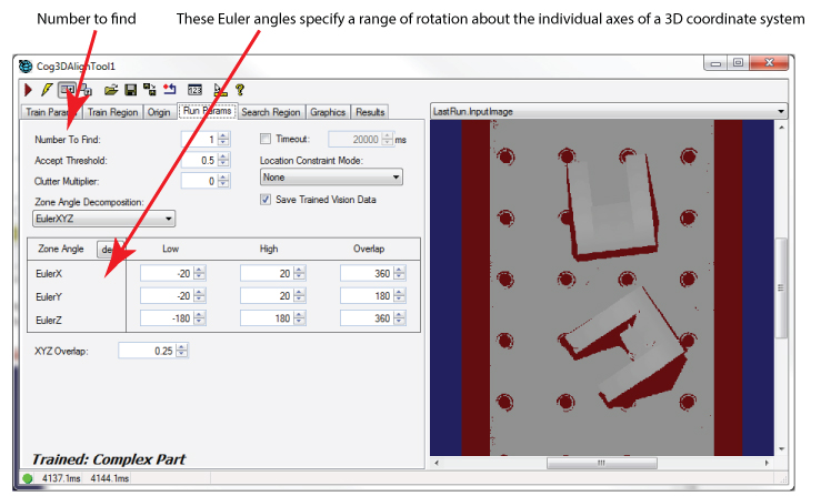
The tool allows you to specify a set of Euler angles to describe the range of rotation and translation the 3D model can exhibit from one 3D range image to the next.
The following run parameters work well for the 3D Align tool in this application:
- Number To Find: 2
- Accept Threshold: 0.3
- EulerX Low: -40
- EulerX High: 40
- EulerY Low: -40
- EulerY High: 40
- Click the Run button and allow the tool to search for the current 3D range image for the trained 3D model.
Select the Results tab to see the results the Cog3DAlignTool generated:
The Cog3DAlignTool should locate two results regardless of which image you are using:
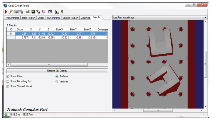
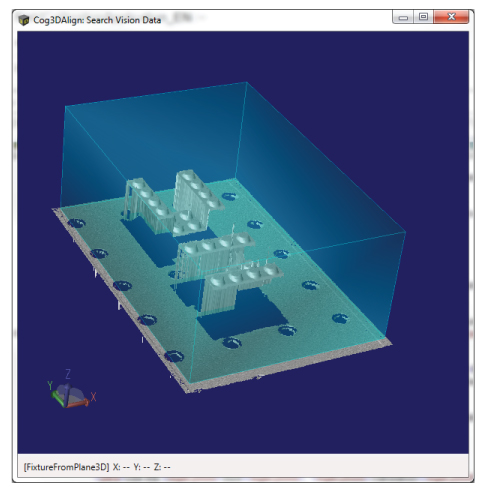
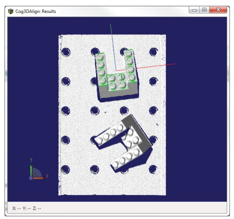
Click Floating 3D Display to see the results in a 3D Viewer:
The Results tab contains a variety of options for graphics in the 3D Viewer:
- Show Pose: Display a graphical set of coordinate axes that reflect the found position and orientation for the pose of the selected result.
- Show Bounding Box: Display a translucent dark green bounding box for the selected result.
Show Trained Model: Display a bright green set of points representing the actual trained 3D model points at their found position and orientation for the selected result.
Be aware the Save Trained Vision Data checkbox on the Run Params tab must be enabled to view this graphic.
In addition, the Results tab gives you the option of displaying the results in Surface or Vertices mode. Surface mode is the default but Vertices mode can display the points of the trained 3D model if desired.
Note: Support for Vertices mode depends on your hardware platform. See the topic About this Release for more information.
- Close the Cog3DAlignTool edit control.
Return to the Job and add a Cog3DFixtureScript CogToolBlock, giving it the 3D range image from your image-database file and the first found pose of the Cog3DAlignTool:
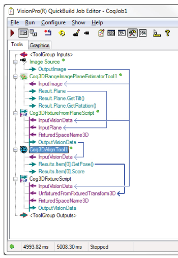
The Cog3DFixtureScript CogToolBlock takes the 3D transform represented by the first found pose result, creates a new 3D coordinate system based on that transform, and then adds it to the original 3D range image. The new 3D coordinate space becomes the SelectedSpaceName3D of the OutputVisionData from the CogToolBlock.
Add a Cog3DVisionDataRerenderTool to the Job and give it the 3D range image generated by the Cog3DFixtureScript CogToolBlock:
The Cog3DVisionDataRerenderTool rerenders a 3D range image in a different coordinate space of its 3D coordinate space tree. Rerendering a range image can improve the effectiveness of other vision tools that later analyze the rerendered image.
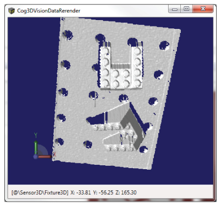
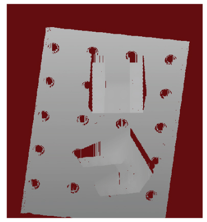
Run the Job again with the second image in the image-database file and select the LastRun.Cog3DVisionDataRerenderTool.OutputRangeImage buffer.
The 3D range image has now been rerendered based on the pose of the first 3D model found by the Cog3DAlignTool:
If you open the Cog3DVisionDataRerenderTool edit control, you can access a 3D Viewer and view the 3D range image that way: