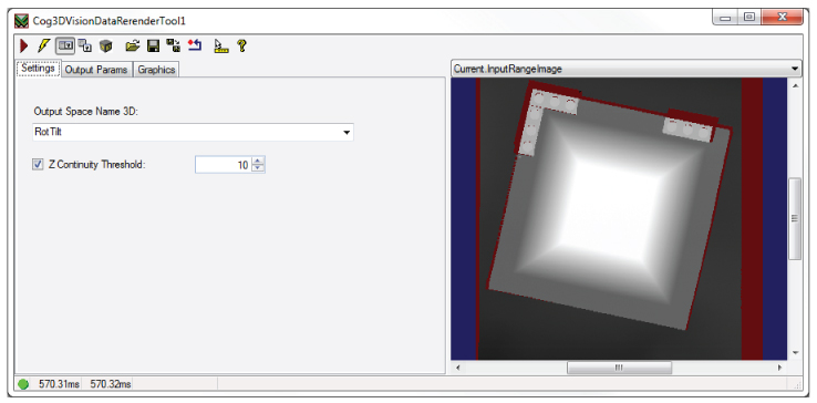
The Cog3DVisionDataRerender edit control provides a graphical user interface to the Cog3DVisionDataRerender tool, which you use to rerender an existing 3D range image based on a different coordinate space of the 3D coordinate space tree. The following figure shows an example Cog3DVisionDataRerender tool edit control:
See the topic Rerendering 3D Range Images for more information on the Cog3DVisionDataRerender tool.
To include the edit control in your custom vision application, you must first add it to your Visual Studio .NET development environment. See the topic Adding Edit Controls to Visual Studio for more information.
This topic contains the following sections.
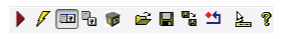
The Cog3DVisionDataRerender tool supports the following buttons along the top of the edit control:
| Button | Description | Function |
 | Run | Rerender the input range image in the selected output space name. |
 | Electric mode | Toggle electric mode, where the tool executes automatically when you change the value of certain parameters. In electric mode, a lightning bolt appears next to every electric property. |
 | Local image display | Open or close the local image display window. A Cog3DVisionDataRerender tool supports the following image buffers:
|
 | Floating image display | Open one or more floating image windows, which support the same image buffers as the local image display window. |
 | 3D Display | Open a 3D Viewer displaying the rerendered 3D range image. See the topic Viewing 3D Range Images with the 3D Viewer for more information on using the 3D Viewer. |
 | Open | Open a VisionPro persistence (.vpp) file that contains a set of saved properties for a Cog3DVisionDataRerender tool. VisionPro reports an error if you try to open a .vpp file for another tool type. |
 | Save | Save the current properties of the Cog3DVisionDataRerender tool to a VisionPro persistence (.vpp) file. The edit control allows you to choose between saving the vision tool with or without its image buffers and tool results. |
 | Save As | Save the current properties of the vision tool to a new VisionPro persistence (.vpp) file. |
 | Reset | Reset the vision tool to its default state. This tool gives you a choice between resetting to the default-constructed state, which is appropriate when you are using it in a Visual Studio.NET application, and its template-initialized state, which is appropriate for QuickBuild applications. |
 | Show ToolTips | Enable or disable the display of tooltips for individual items in the edit control. |
 | Help | Open this VisionPro Software Documentation file. |
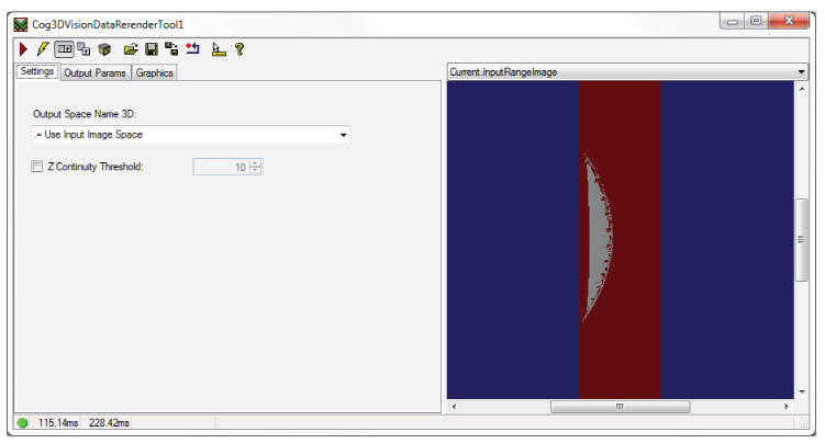
Use the Settings tab to set the name of the 3D output space to render the new 3D image and to enable a threshold value that determines if neighboring pixels are deterined to be part of the same continuous surface or not.
| Parameter | API | Description |
| Output Space Name 3D | OutputSpaceName3D | The name of the 3D space in which the output range image will be rerendered. |
| Z Continuity Threshold | OutputImageZContinuityThreshold | If enabled, neighboring pixels that have a height value greater than the set threshold parameter will be rendered as disconnected and not part of the same continuous surface. A discontinuity can affect the results of other 3D tools that analyze the output range image. |
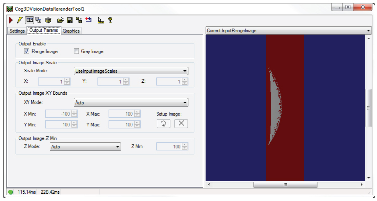
Use the Output Params tab to set a variety of parameters related to the rerendered output image.
| Parameter | API | Description |
| Output Enable | OutputEnable | Determine if the tool generates a rerendered 3D range image, a rerendered 16-bit greyscale image, or both. |
| Output Image Scale | OutputImageScaleMode | Control the scale of the rerendered image, using the scales of the input 3D range image or use custom (X, Y, Z) scale values. |
| Output Image XY Bounds | OutputImageXYMode | How to define the (X, Y) bounds of the rerendered image. either automatically or using specific boundaries along the X-axis and Y-axis. The section Rerendering 3D Range Images describes how to use a setup image to determine the dimensions of the output image if you choose to limit the rerendered image to a specific boundary. |
| Output Image Z Min | OutputImageZMode | Switch off the default Auto mode if you want to enable a OutputImageZMin parameter and set a value closer to the expected minimum height based on your production environment. |
Use the Graphics tab to choose which graphics the tool makes available.
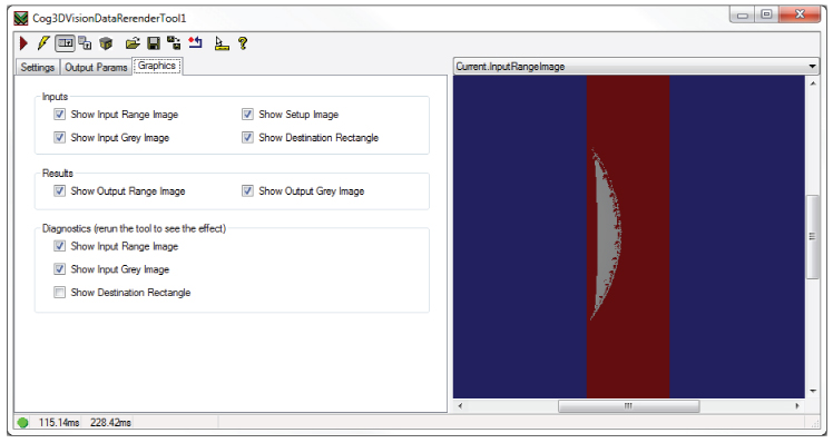
| Inputs | Choose to generate a record for any of the following images and graphics:
|
| Results | Choose to generate a record for any of the following output images:
|
| Diagnostics | Choose to generate a record for any of the following images and graphics based on the last execution of the tool:
|