This topic contains the following sections.
This topic describes how to use synthetic PatMax. Synthetic PatMax refers to the training of PatMax patterns using collections of shape models instead of a training image. Synthetic PatMax lets you create patterns based on CAD data, shapes that you synthesize from your own numeric data, or shapes that you extract from an image using Model Maker.
Regardless of where you obtain the shape models that you use for PatMax shape training, the overall procedure follows these basic steps:
- Create a CogPMAlignTool object.
- Configure it for shape training
- Populate the CogPMAlignTool's CogPMAlignPattern's TrainShapeModels with shapes.
- Train the shapes and evaluate the training results
- Run the tool and evaluate the alignment results
This topic describes each of these steps in detail.
The following steps are illustrated using QuickBuild and the CogPMAlign tool edit control. You could perform the same actions shown below using the programming interface.
Configure the Job's Image Source to acquire images from a camera or from an image database, and create a new CogPMAlignTool.
Whenever you create a CogPMAlignTool object (or a CogPMAlignPattern object, if you are using the operator level interface), the CogPMAlignPattern contains an empty CogShapeModelCollection. You do not need to create this collection, only add the shapes you wish to train to it.
In almost all cases, you should also create a calibration tool, typically a CogCalibCheckerboardTool to add a calibrated space to the acquired images. Whenever you work with shapes, the shapes' geometric properties (size and location) are expressed in a coordinate space. Since these shapes almost always refer to physical objects, you should specify these properties in physical units. Creating a calibrated space allows PatMax (and you) to associate the shape's geometric properties with locations in an acquired image.
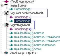
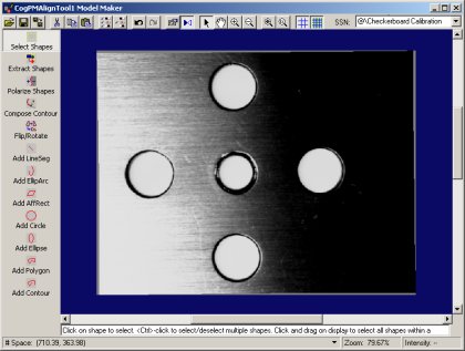
The following figure shows a typical QuickBuild configuration for using synthetic PatMax:
This section contains the following subsections.
- Specify an Appropriate Training Mode
- Specify No Training Region
- Specify An Appropriate Pattern Origin
- Grab a Calibrated Training Image
There are several PatMax parameters that need to be specified before you can use shape training or synthetic PatMax:
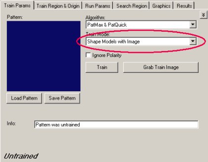
By default, PatMax trains patterns using the pixels in a training image. To use shape training you must specify either Shape Models with Image or Shape Models with Transform for the train mode. The difference between these two methods is how shapes dimensions are related to pixel coordinates. Generally, the simpler method is Shape Models with Image, where you supply a TrainImage that contains a definition for the selected space of all of the supplied shapes.
The TrainRegion lets you limit the portion of an input image that is used for training. While you can also use an input region to limit which shapes in the shape model collection are trained, in most cases it is simpler to just create or import only the shapes of interest and set the training region to None.
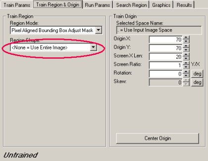
Note: If you do specify a training region, the TrainRegionMode must be CogRegionModeConstants.
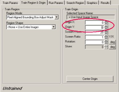
The default pattern origin is 70, 70. This is expressed in the selected space of the training image, and if you are using a calibrated space, this may not be a reasonable value. In general, you should specify an origin that is near the center of your collection of shapes.
Before you can create shapes with Model Maker using the Shape Models with Image training mode, you must Grab a training image. Model maker displays this image as you create and edit shape models, and you can use the pixels in this image to polarize the shapes you create, but PatMax will not use the pixels in this image for pattern training. The image that you supply should be calibrated and it must include a definition of the selected space of the shapes you will be using.
Once you have grabbed the training image, the Model Maker button

Keep in mind that Model Maker always displays the current collection of shape models in the associated CogPMAlignPattern; you do not need to take any action to update or save the shapes you create in Model Maker. Whenever you save the state of the underlying CogPMAlignTool, the shape models are saved as well, as part of the tool. Additionally, Model Maker lets you save shape collections separately.
This section contains the following subsections.
Aside from whether or not to consider polarity, which you should enable if all of your shapes are polarized and disable otherwise, the only CogPMAlignTool training-time parameters are the coarse and fine granularity limits and elasticity. By default, PatMax automatically computes the granularity limits. In some cases, these computed granularity limits may be too large. Before training, you should enable the display of the computed limits by clicking the chevron button
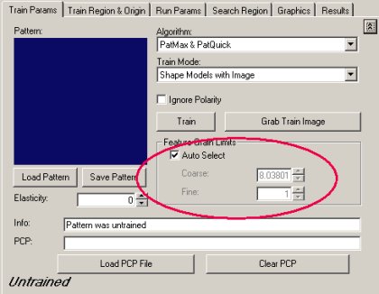
After you train the pattern (by clicking the Train button), display the Current.TrainImage, and check the Show Coarse checkbox in the Graphics tab to evaluate the trained features.
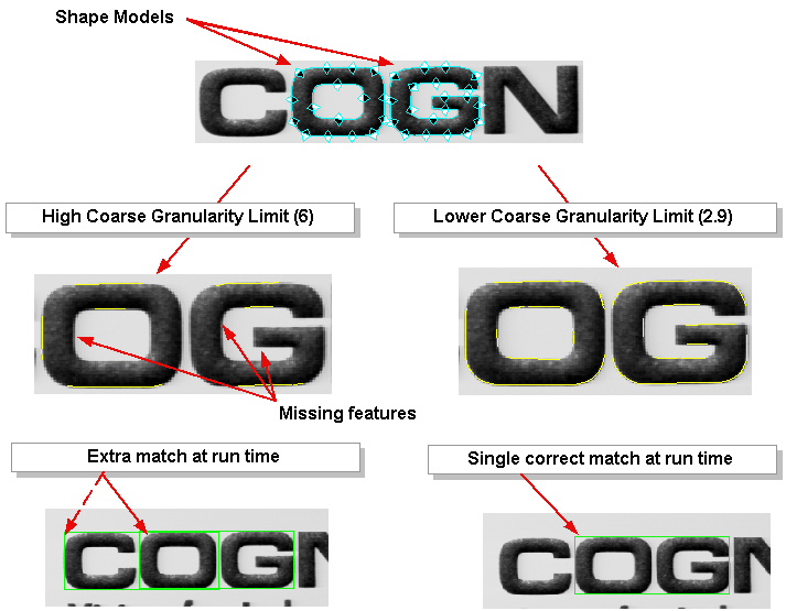
In particular, pay close attention to the coarse feature display. If the computed coarse granularity limit is too high, there may be too few coarse features to train an effective pattern, or in some cases the coarse features may create degenerate search results, as shown in the following figure:
Note: You must re-train the pattern after changing the granularity limits.
This section contains the following subsections.
Once you have completed the process of training your pattern, you should run it on a representative selection of run-time images, after specifying appropriate run-time parameters.
Note: Make sure that the run-time images are calibrated using the same calibration data as the training image.
By default, PatMax penalizes pattern matches in run-time images where the matched pattern contains any extra features. In most cases, your run-time images will contain many features that are not present in your shape model collection. For example, shadows, reflections, texture, and surface irregularities may be present in run-time images but are unlikely to be in your trained pattern. For this reason, your pattern may receive very low scores unless you disable this PatMax feature.
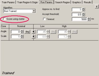
Note: If you use the PatQuick algorithm, score using clutter is automatically disabled.
Due to variations in lighting and the position of objects in the scene being acquired, it is likely that there will be slight size and angle differences between the trained shapes and the features in run-time images. For this reason, you should generally enable both the angle and scale degrees of freedom:
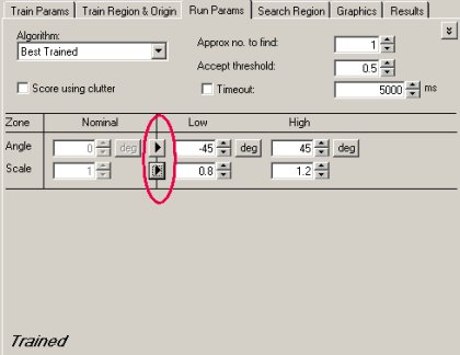
Note: If you enable the independent X-scale and Y-scale degrees of freedom, the alignment will use the less accurate PatQuick algorithm.
In most cases, if you expect the run-time images to be close in size and rotation to the trained pattern, you can enable a narrow range for these degrees of freedom. If you are using PatMax to measure the variance from the pattern to the part in the run-time image, then the range should be larger.
Note: You should not attempt to specify large values for the expected scale difference between the shapes in a trained pattern and the features in a run-time image unless you need to search across a wide range of size variation.
After configuring the run-time parameters and running the tool, carefully evaluate the results of the alignment operation. If the tool fails to find the pattern in the run-time image, if the reported pose is inaccurate, or if the result has a low score, reduce the accept threshold and enable the display of matched features by checking the Show Match Features check box in the Graphics tab and re-running the tool.
The match feature display will indicate the match quality for all the pattern's trained features (green for high quality, yellow for fair quality, and red for poor quality or missing features).
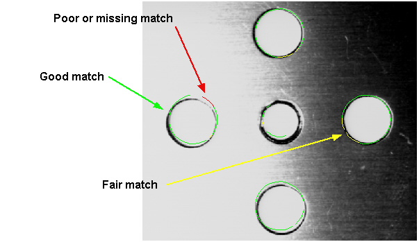
Usually, you can use this information to determine why the pattern is not scoring well or not being found. In the case of the figure shown above, it appears that the pattern does not accurately represent the part's features. You could improve the score of this match by specifying a nonzero value for the Elasticity value.