This topic contains the following sections.
- Prepare the DXF Files for Import
- Understand Coordinate Space Issues
- Create an Appropriate Coordinate Space for Import
- Use the Checkerboard Calibration Tool To Calibrate a Physical Space
- Use a Fixture tool to correct for Additional Scale
- Import the Shapes
- Polarize the Shapes
- Step 1: Train the pattern without polarity
- Step 2: Enable appropriate degrees of freedom and align
- Step 3: Apply the alignment result pose as a new fixtured space
- Step 4: Select the new fixtured space in Model Maker
- Step 5: Polarize the shapes
This topic describes how to import shapes from DXF files to use for shape trainingCogPMAlignPattern objects. You can use the techniques described in this topic with the Model Maker control or using the programming interface implemented by the CogCADFile object.
Importing and training shapes from a DXF file lets you create a highly accurate pattern for a physical object, based on the dimensions used to create the object.
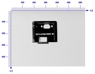
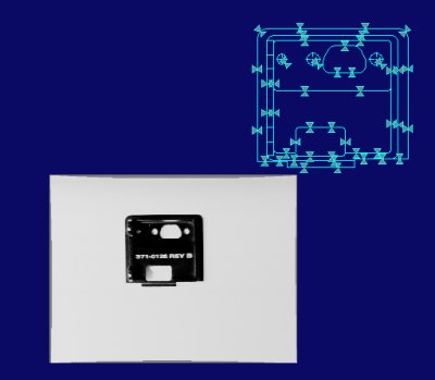
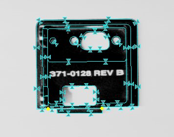
A typical DXF file includes graphics that describe many things in addition to the shape and dimensions of the part of interest, including text labels, arrows, borders, and legends. The following figure shows a typical DXF file:
In the case of this DXF file, the part of interest is the rear camera plate:
The remaining shapes in the DXF file are extraneous features; they will not appear in the run-time images of the part. There are several methods that you can use to create a simplified DXF file containing just the features of interest:
- If you have access to the CAD application that was used to create or export the DXF file, you can use that application to assign the features of interest to a specific DXF layer or AutoCAD group, then you can import just that layer or group.
- If you have access to the CAD application that was used to create or export the DXF file, you can use that application to simply remove the extraneous features from the file.
- If you cannot modify the DXF file, then you can import all of the shapes into Model Maker and manually delete the extraneous shapes.
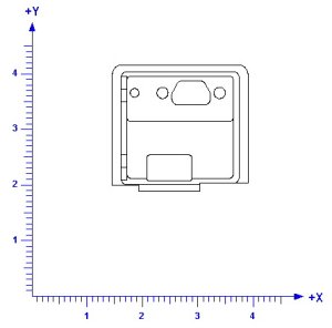
The shapes in a DXF file are defined by their geometric properties: their locations and dimensions. These numerical values are expressed within a single coordinate space that is defined for the DXF file as a whole. In almost all cases, the coordinate system used in a DXF file is a right-handed system with its origin at the lower-left corner of the drawing and with units equal to one inch. The following figure shows such a coordinate system superimposed on a DXF file:
If you create a DXF file that contains only the features of interest from within the initial DXF file, the new DXF file will typically have the same units and handedness, but the origin may be reset:
The default coordinate space ("@" or root space) for an uncalibrated VisionPro image is a rotated left-handed coordinate system with its origin at the upper-left corner of the upper-left pixel of the image and with units equal to one pixel. The following figure shows such a coordinate system superimposed on an image:
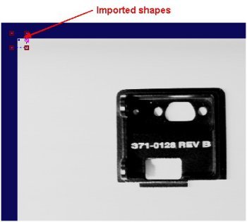
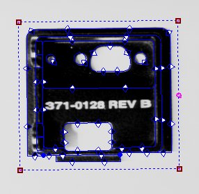
When you import the shapes from a DXF file using Model Maker, the control automatically assigns the imported shapes the currently selected coordinate space in the image displayed by Model Make. (If no image is being displayed, then the imported shapes have their selected space set to "#".) If you import shapes in an uncalibrated image, the shapes will have their selected space set to the "@" space. Because of the large scale difference between the typical DXF coordinate space and "@" space, the imported shapes will be very small relative to the pixels in the image:
By zooming in on the shapes, you can also see that the shapes are upside-down relative to their arrangement in the DXF file:
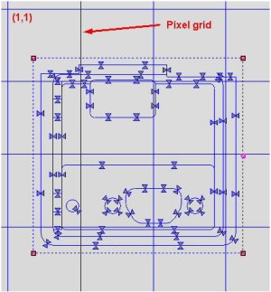
Also, note that the locations of features in the imported shapes relative to the image pixel grid correspond to the locations of the features in the DXF coordinate system, shown earlier.
In almost all cases, you are importing shapes from a DXF file so that you can locate an image of the associated object or part in an image. The most effective technique is to create a calibrated coordinate space, and then use that space when importing the shapes. This technique is described in this section.
The first step is to create a calibrated space that reflects the physical units defined in the DXF file. If you have access to the camera, physical, and optical configuration you will be using to acquire images, then the simplest method of creating a calibrated space is to use the CogCalibCheckerboardTool to create the calibrated space. You do this by constructing a checkerboard calibration plate where the tile size is known in the physical units, then placing this plate at the location where the parts will be, acquiring an image, and computing the calibration. Once the calibration has been computed, each time you run the tool, it will apply the calibrated space to its input image.
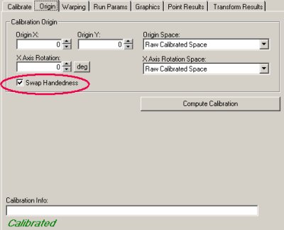
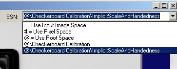
You can also use the Checkerboard Calibration tool to correct for the handedness difference between the DXF file coordinate space and "@" space by checking the Swap Handedness checkbox in the Origin tab:
If you are not able to acquire images using the same configuration you will be using to acquire images in production, you can use a CogFixtureTool to create a calibrated space.
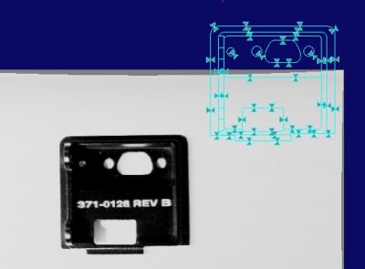
If you attempt to import shapes from a DXF file using an image calibrated as described above, the imported shapes may still not correspond to features in the image:
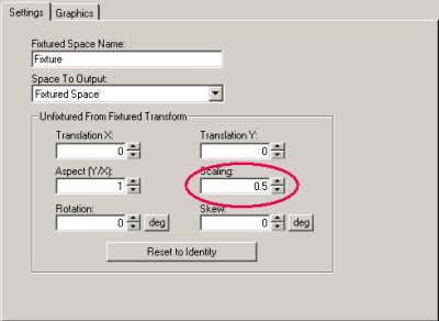
Note that the shapes appear to be approximately twice as large as the part in the image. The scale difference is caused because of the implicit scale of the DXF shapes. Most CAD drawings have an implicit scale value, typically represented as part of the drawing's legend:
Information about this implicit scale value is not recorded in the DXF data; you must manually determine and correct for this value.
You can correct this scale difference using a single CogFixtureTool. Simply create a fixture tool and specify a scale value of 0.50 (to reflect the implicit DXF scale), and run it to apply a new space to the existing calibrated space:
If you select the newly adjusted space before importing the shapes, the resulting shapes have the correct orientation and size:
Once you have defined the appropriate coordinate space for importing shapes, simply click the Import/Open button in Model Maker and select the DXF file or files to import. You should keep in mind that the selected space that you have selected in the Model Maker space popup menu Is applied as the selected space to each shape as it is imported and converted from the DXF file. Also, the shape connection and spline approximation tolerances are affected by the space you select here.
Model maker displays a dialog box that lets you select which DXF layers and groups you wish to import.
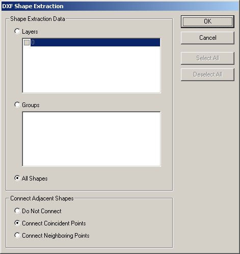
The dialog box also lets you control how Model Maker will connect discrete DXF shapes to form VisionPro contour shapes. In general, you should specify Connect Neighboring Points (which will connect all shapes' endpoints that lie within 0.25 pixels of each other, when mapped through the space selected in the SSN menu).
Note: If your DXF file contains many small shapes which are very close to each other, using the Connect Neighboring Points option can produce inappropriate or degenerate connected shapes, such as line segments which have the same start and end point. If you experience this type of error, either modify your DXF file to include fewer, larger shapes, or specify the Connect Coincident Points option, which will only connect shapes with endpoints that touch each other.
After you import the shapes from the DXF file, you may want to polarize the shapes. PatMax will generally be quicker, and more able to make accurate matches, if the shape models you train are polarized and their polarities match the feature polarities in the run-time image.
If you have access to an image of the part, and the image exhibits appropriate polarity information, you can easily use that image to polarize the imported shapes. While you can adjust the position of the shapes by hand to match the image features, it is simpler and more accurate to use PatMax to align the features without polarity, then use that alignment to do the polarization. This procedure is described in the following sections.
If you have followed the procedures described above, your Model Maker display should contain a set of shapes which match the handedness and scale of the features in your image, although the image features may be rotated and translated relative to the shapes:
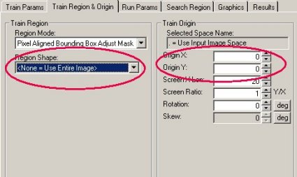
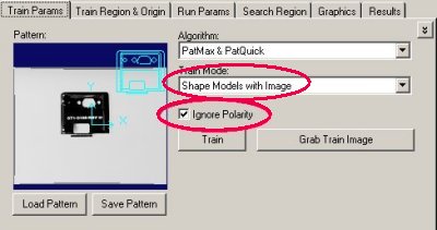
Open the CogPMAlign tool edit control, and specify the following parameters: Shape Models with Image for the training mode, no training region, and an origin of 0,0:
Make sure the Ignore Polarity checkbox is checked, and train the image:
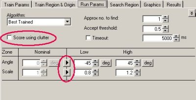
In most cases, the acquired image will have the part or object at a slight angle from the image coordinate system, and it may exhibit a slight scale difference, due to manufacturing variations or small calibration errors. Accordingly, you should enable the angle and scale degrees of freedom before trying to locate the part. Also, in most cases you should disable clutter scoring, since the image will likely have many features not present in the imported shapes, such as shadows and reflections.
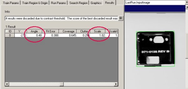
Run the tool and verify that it found the part in the image:
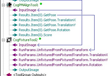
Now create a CogFixtureTool below the CogPMAlignTool. Simply connect the output pose for the CogPMAlign tool's first result to the input transformation, then run the CogFixture tool. This will add the new transformation to the image's coordinate space tree.
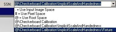
Because the image is passed by reference from tool to tool in a VisionPro tool group, the new coordinate space is now present in the CogPMAlignTool's training image. Open Model Maker and select the new space:
Model Maker will ask whether you want to map the shapes into the newly selected space. Answer Do Not Map; Model Maker will display the shapes in the new, fixtured space. The shapes should now be aligned with the image features:
Now click the Polarize Shapes button in Model Maker. Model Maker will polarize all shapes where the corresponding image features have sufficient contrast to determine the polarity:
You may need to manually polarize some shapes. If you click on the 'show shapes with indeterminate polarity' button, Model Maker will select only those shapes with indeterminate polarity:

Before training the polarized shapes, you should re-select the calibrated space using Model Maker's SSN popup menu. As before, do not map the shapes when changing the space.