This topic contains the following sections.
- Creating Shape Models for Simple Objects
- Step 1: Create a Calibrated Coordinate Space
- Step 2: Draw and Polarize the Shapes that Make Up the Part using Model Maker
- Step 3: Set the Pattern Origin and Train the Pattern
- Step 4: Search for the Pattern
- Drawing Shapes to Match Image Features
- Model Large, Regular Features
- Use PatMax Image Training to Estimate Feature Locations
This topic describes how to create shape model collections using Model Maker's drawing tools for PatMax shape training, as opposed to using the shapes produced by the Shape Extraction package.
A common situation in which it is appropriate to create your own shape models is when you have precise geometric information (but no CAD file data) about an object, and the object is relatively simple. In other cases, you may find that you are unable to use shape extraction to produce good shapes, due to the presence of image defects or artifacts and you may not have any geometric data. When this happens, it may be possible to attempt to draw features by hand, based on the image features.
Consider an example in which you wish to create a trained PatMax pattern for a simple part:
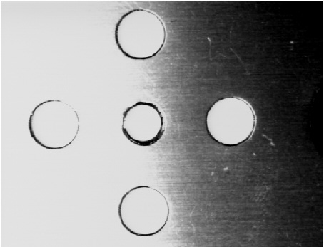
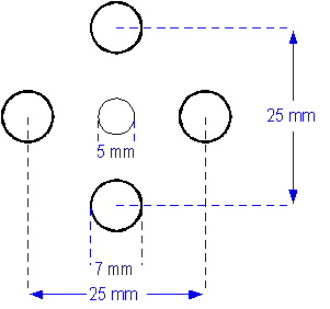
The part is so simple that it is easy to create a geometric description of the part by measuring it:
To create a shape model for this pattern, you would follow the steps listed below:
The dimensions that describe the part of interest are made using some type of physical units. In the case of this example, the measurements are in millimeters. Before you can create shapes that correspond to the part, you must define a coordinate space that lets you map between the real-world units (millimeters) and image pixels.
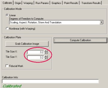
The simplest way to create this calibrated space is to acquire an image of a checkerboard calibration plate using the same optical and mechanical configuration you will use to acquire an image of the part. By entering the size of each tile in millimeters into a CogCalibCheckerboardTool, you can construct such a calibrated space. (The checkerboard calibration tool can also automatically unwarp the acquired image to remove radial and perspective distortion.)
Create a CogPMAlign Tool and grab a calibrated image as the tool's training image. The image you use as a training image does not need to contain an image of the part; you only need the image for the calibrated space.
Open Model Maker, select the calibrated space in the SSN popup menu, and create 5 circles of the correct size and position. The simplest way to do this is to draw a circle, then open the property page for the circle and enter the appropriate values:
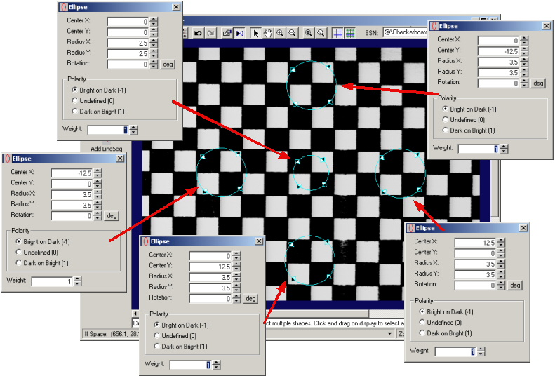
Note: It is not possible to draw a circle using Model Maker if you have selected a calibrated space; if you draw a circle using the Add Circle button, Model Maker creates an ellipse with the X-radius and Y-radius set to the same value.
In this example, the calibrated coordinate system has its origin at the center of the image. For simplicity, the example shows the pattern centered on the origin of the coordinate system:
At the same time you set the shapes' geometric properties, you can also enter the shapes' polarity and weight.
Note: Model Maker only displays a single shape edit window at a time. The preceding figure shows all five windows for clarity. In practice, you would leave the window open and switch from shape to shape by clicking on the next shape.
Once you have created the shapes, return the CogPMAlign tool edit control and train the pattern. In most cases, you should specify a pattern origin of 0,0 and no pattern training region:
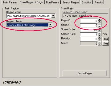
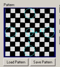
The Pattern display in the Train Params tab displays the trained shapes and origin:
To verify that the pattern trained correctly, run the tool supplying a calibrated run-time image of the part:
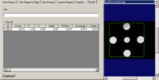
You may find that even when the pattern shapes are very accurate that image defects or artifacts such as shadows or reflections may cause reduced scores or poor-accuracy matches.
If you cannot extract good features from an image, and you do not have access to a geometric description of the object you wish to train, you can attempt to draw the shape models by hand.
In general, this procedure is unlikely to produce PatMax patterns that will produce accurate results or consistent scores for the following reason: Under optimal conditions when using image training, PatMax can produce alignment accuracy of 0.10 pixel or better at run time. This accuracy is based, in part, on PatMax's ability to make very accurate sub-pixel determinations of the locations of feature boundaries in images. When you draw shape model features in an image, your ability to position a feature boundary accurately is limited to 1 or 2 pixels. This inaccuracy will limit PatMax's ability to perform an accurate alignment. Further, if you add hand-drawn features to a shape model collection produced by extracting shapes, the different accuracy levels for different shapes will tend to produce low scores and reduce the accuracy of the results.
In circumstances where coarse-accuracy alignment is sufficient (such as part counting), however, drawing shape models by hand can produce PatMax patterns that can be trained and located at run time.
If you decide to draw your own shapes using Model Maker, the guidelines described below may help you produce more effective patterns.
The first step in any PatMax alignment is the coarse alignment of the pattern using large features. The most reliable features for coarse alignment tend to be large, regular features such as straight lines, circles, and arcs. The following figure shows how a pair of circles can be used to quickly model the large circular features of a part:
When this simple pattern is trained, then used to locate the part under a variety of lighting conditions (with Score Using Clutter disabled), it produces the following results:
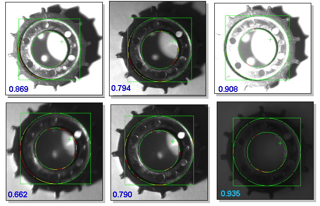
Note that the accuracy of these results is low. Also, the nature of the pattern makes it impossible to measure the angle of the part.
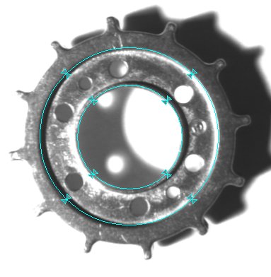
You may be able to improve the accuracy of your alignment results by using PatMax image training to estimate the true locations of image features. You can do this by temporarily switching the Train Mode to Image, training the image, and then examining the trained feature display, as shown in the following figure. To make sure you obtain the most accurate feature locations, set both the coarse and fine granularity limits (in the Train tab) to 1.0 before training.
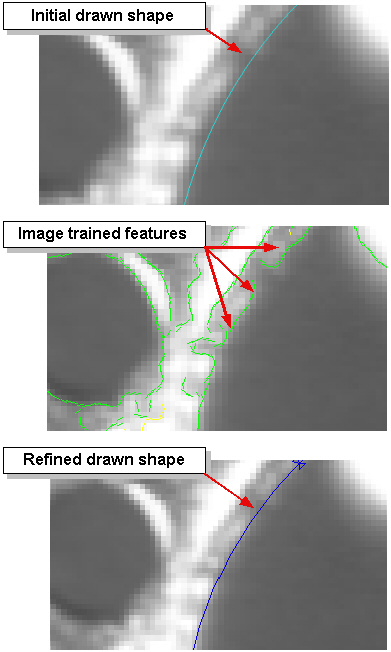
Keep in mind, however, that the feature location determined by PatMax image training is specific to that image. If changing lighting conditions cause the apparent location of the feature to move, you may need to use this procedure on a variety of images.