This topic describes the steps necessary to acquire images from a Cognex DS900 laser displacement sensor.
Prerequisites:
- The Vision Controller or the PC is powered up and configured with Cognex VisionPro software.
- Any electrical connections to the DS900 are correctly made (e.g. encoder).
Refer to the DS900 Series Displacement Sensors Quick Reference Guide (see Appendix B) for instructions on connecting the hardware.
See the following sections for more information:
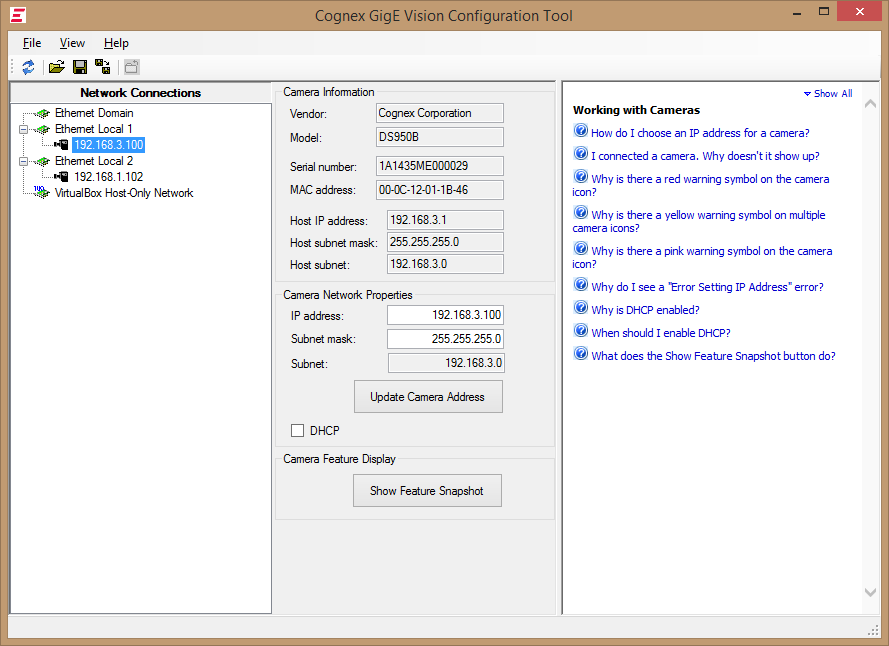
Configure the IP Address of the DS900
Start Cognex GigE Vision Configurator. Please see Appendix B to launch the Configurator if it is not present on your desktop. Follow the instructions in the GigE Vision Cameras User’s Guide (see Appendix B) to configure the IP address of the unit.
Launch VisionPro® QuickBuild software
Start QuickBuild, by double-clicking the VisionPro® QuickBuild icon.
Initialize the DS900 sensor as an acquisition source
- Within the QuickBuild workspace, locate and double-click the Image Source entry under CogJob1.
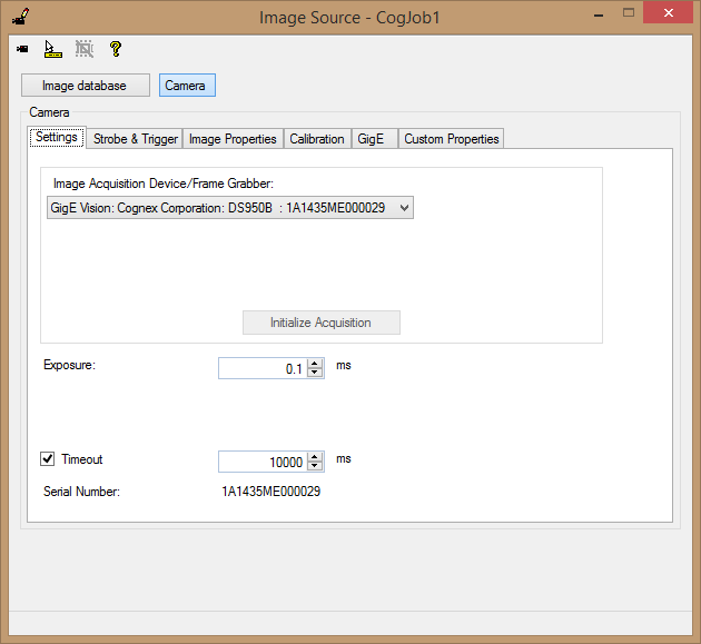
- In the Image Source dialog, select the Camera as the source.
- In the Image Acquisition Device drop-down, locate the DS900 device and click Initialize Acquisition.
Configure the acquisition settings
Continue to the next section below, entitled Configuring DS900 Acquisition.
This section will describe the settings for the various parameters present in the various tabs of the acquisition configuration interface.
Settings tab
Exposure
The value of exposure (in milliseconds) should be set depending on the material that is being scanned. The recommendations are as follows:
Table 1: Recommended shutter times (approximate)Target Material Shutter times White paper/plastic 10 - 50μs Colored plastic 50 - 100μs Metallic surfaces 0.1 - 1ms Black plastic/rubber 0.5 - 1ms Timeout
If enabled, this setting (in milliseconds) should be set greater than the sum of the following three factors:
- The maximum time between the acquisition request and the start of acquisition (perhaps due to a delay in starting motion when an encoder is used);
- The maximum time taken to scan the part (controlled by the speed of motion and length of the scan); and
- The maximum time taken to complete image data transmission after the scan has completed.
Strobe and Trigger Tab
Trigger mode
The only two supported modes are Manual and Free Run. The DS900 series sensors do not support hardware triggering. Free Run mode may enable the acquisition to support a slightly higher line rate. Setting Auto and Semi puts the system into an equivalent state as Free and Manual, respectively.
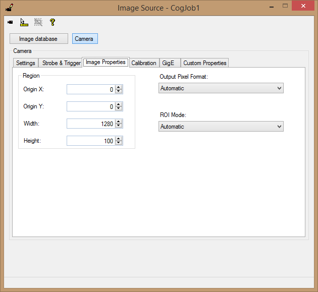
Image Properties Tab
Region
The Origin X and Origin Y parameters should always be set to zero. The Height parameter can be varied depending on the length of product being scanned but should not be bigger than 64000. The appropriate value can be estimated by the formula below:
Acquisition Line Rate * Product Length / Motion Speed
Output Pixel Format and ROI Mode
Use the default value for both (Automatic).
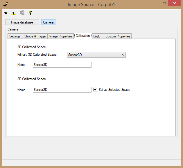
Calibration Tab
Use the default parameters.
- Primary 3D Calibrated Space: Sensor3D,
- 2D Calibrated Space Name: Sensor2D,
- Selected Space: checked.
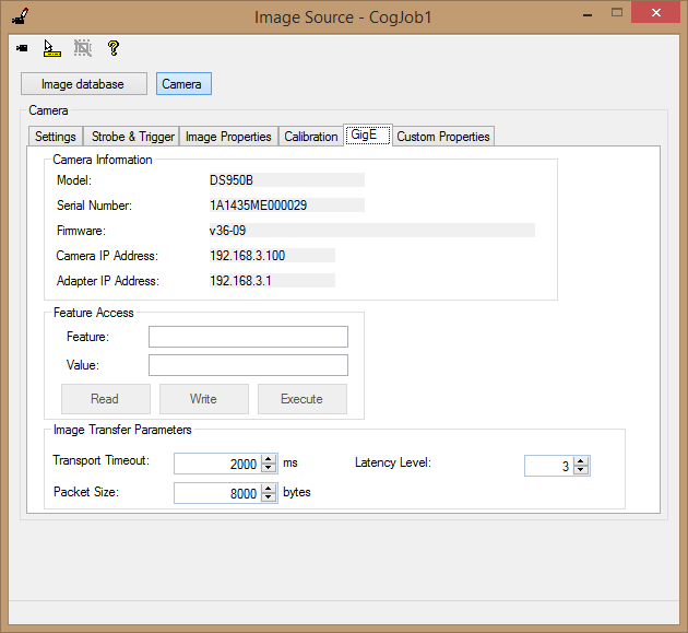
GigE Tab
Feature Access
This section can be used to set or query various GigE features. It is highly recommended to not use this section to set GigE features, as doing so may cause unpredictable results and even possibly the acquisition to become unresponsive and unrecoverable. However, GigE features can be safely queried. To perform the query, simply type the feature name into the Feature text box and press the Read button. The value of that feature is then returned into the Value text box.
Transport Timeout
This value is similar to the Timeout value on the Settings tab, except that the pre-acquisition time does not need to be included. It is recommended that this be initially set to 20000 milliseconds. Note that in the event that the timeout is hit, the following acquisition error message will be returned: “The acquisition failed abnormally. (Buffer retrieve failed (MISSING_PACKETS))”
Generally, it needs to be set to a value that is longer than the time it takes for the longest acquisition expected. If an encoder stops for a time then continues, the idle time must be included in the estimate for Transport Timeout.
Packet Size
Setting this value has no effect in case of DS900 acquisition, as it is internally controlled by the Cognex acquisition driver.
Latency Level
This value should be left at its default value of 3.
Custom Properties Tab
This tab is used to set various camera parameters that are not available in other tabs.
In the case of the DS900, there are many important parameters that need to be set using this method. Each parameter will be outlined below. Parameters are added using the Add New button ( ) located above the feature list. Parameters are removed using the Delete button (
  ) located above the feature list. The order of parameters in the grid determines the order in which they get written to the camera. This order does not matter in most cases, but may have effect when non-default parameters are added which can influence each other on setting. The following table lists the parameters that should be used to configure correct acquisition. Optional parameters are labeled as such.
| Please do not use the red parameters! |
| DS900 Category | 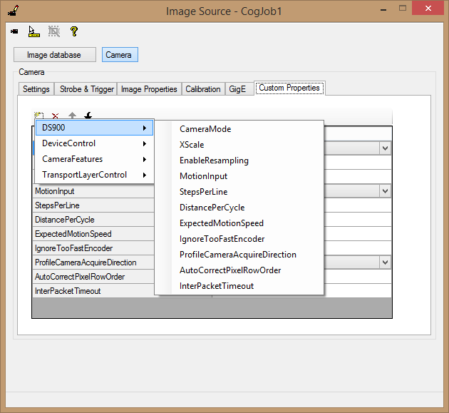 | ||
CameraMode |
| ||
| XScale | A type double used to set the scaling factor for the image in the X direction (horizontal). Lowering the XScale causes the data to fill more image width. It does not change the output image size, which remains at the provided pixel value (Image Properties Tab | Width parameter). | ||
| EnableResampling | When enabled (default), the acquired image will be resampled to produce the desired X scaling. When disabled, the image will be returned to the user as acquired (1280 pixels wide, as a recommended setting). Since the default value is true, all range images will be resampled. | ||
MotionInput |
| ||
| StepsPerLine | This setting should be used to control the ratio of the encoder pulses to lines being acquired. Increasing this value reduces the rate at which lines are acquired by the sensor. The default value is 4. | ||
| DistancePerCycle | Millimeters of motion between acquired lines. This is set by the encoder specifications, reduced per the StepsPerLine parameter. For square pixels this value must match the XScale parameter value. The default value is 1. Changing DistancePerCycle will not alter how the range image looks. This property does not affect image scaling in any way. To achieve “square pixels”, the XScale per pel must match what is actually being acquired in Y per pel. Changing this property won’t affect that. | ||
ExpectedMotionSpeed | This should match the physical speed of the motion stage, in millimeters per second. The default value is 200.
| ||
| IgnoreTooFastEncoder | When enabled, the acquisition line rate will be limited to what the camera is capable of acquiring. When an external encoder is used and the encoder is driven too fast, the acquisition will effectively become controlled by a time based encoder. The default value is False, so that encoder rates that are too fast will be flagged as errors. Note that encoder direction, encoder resolution, and single channel encoder are not configurable on the DS900. If this parameter is disabled, the acquisition will throw an encoder overrun error (if the encoder pulse rate exceeds the maximum acquisition frame rate). Enabling this parameter causes missed encoder pulses to be ignored. Missing lines will not be generated on the DS900 series for VisionPro 8.4. | ||
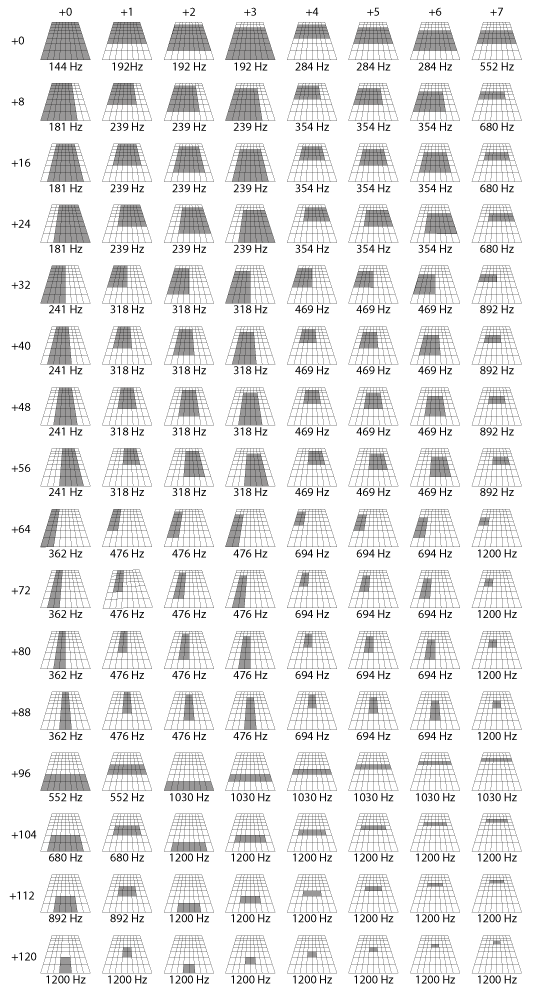
| MeasuringField | Controls which portion of the trapezoid scan area is the data returned from. Please refer to Measurement field lookup table to determine the value that needs to be set. The default value is 5. | ||
| Threshold | Pixels on the scan profile that meet or exceed the threshold value are used to produce the range image. Pixels below the threshold are considered missing. The range is 0 - 255. The default value is 128. | ||
| ThresholdDynamic | Allows the sensor to automatically adjust the threshold across the profile to achieve improved results by allowing different thresholds at different portions of the profile. The default value is OFF. | ||
| ProfileCameraAcquireDirection | When set to LaserToLens, will adjust the image transform and optionally flip the image vertically to correct mirror imaging. The default value is LensToLaser. | ||
| AutoCorrectPixelRowOrder | When True (default) and ProfileCameraAcquireDirection is set to LaserToLens, the acquired range image will be flipped vertically to remove mirroring. | ||
| InterPacketTimeout | Ccontrols the maximum interval of how long the driver will wait between packets before timing out. Since the DS9xx Sensors send packets as they are being acquired, any stoppage of extreme slowing of motion when using the encoder will cause acquisitions to fail. The default is 1000 mSec. | ||
| LaserMode |
SUMMARY:
| ||
| LaserDelay | Specifies a delay time, in seconds, between laser turn on and the start of acquisition. The default is 0.005 (5 mSec). An acquisition error will occur if the delay is set to longer than 1 second. Setting LaserDelay to 0 results in no delay. | ||
| CameraFeatures Category | AlgorithmControl | 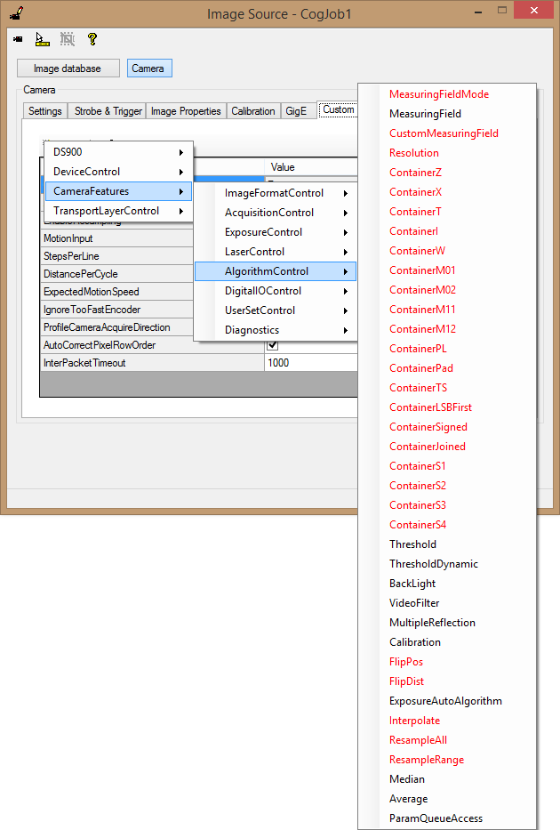 | ||
| Median | Defines a kernel size for a median filter to be applied to the profile to assist in smoothing and noise reduction. Possible values are disable, Median3, Median5, and Median7. The default value is disable. | ||
| Average | Defines a kernel size for an averaging filter to be applied to the profile to assist in smoothing and noise reduction. Possible values are disable, Average3, Average5, and Average7. The default value is disable. |
| After changing any custom parameter, it is critical to click on a different parameter so that the modified row loses focus in order for that change to take effect! Clicking on a different tab also sets the properties. |
View the profile: Go to the Custom Properties tab and set the CameraMode property to Intensity. Start live video, fit the image to the display, and then raise/lower the camera until a stripe/profile of the target part is seen in the middle portion of the image. Close the live video window and set the property back to Range.
 Note
NoteThe measuring field used for Intensity mode is measuring field 0, which is not the default for Range Mode acquisition. - Go to the Custom Properties tab, and set the MeasuringField property to 0. This enables processing of data in the entire measuring trapezoid.
- Keep the MotionInput setting in the default SimulatedEncoder state, and acquire a Range image. Observe whether or not data is missing. If data is missing, it may be due to the exposure being too low and/or the Threshold setting being too high. For many applications an exposure of 0.5 is appropriate. Also, it is not unusual to reduce the threshold from the default value of 128 to 64 or lower. The Threshold can be adjusted on the Custom Properties tab. Change the Exposure or Threshold and re-acquire, until you achieve a good image.
- Narrow your measuring field to achieve higher scan rate. If the scanned profiles may only appear in a specific segment of the working section, you can set a non-zero MeasuringField value in Custom Properties, using Appendix A below. Acquire images of your part and refine your MeasuringField. (You may still use the Simulated Encoder even if you will be using a physical encoder). Make sure that all sections of the part are visible. For dimensions of the working section of your DS900 unit, refer to the DS900 Quick Reference Guide.
Define Y coordinate space of the Range image. The acquisition line rate and the generated Y coordinate axis depends on the following parameters: DistancePerCycle, StepsPerLine and ExpectedMotionSpeed. The ExpectedMotionSpeed property only applies if you are using a simulated encoder. (In case of using a physical encoder the speed of acquisition is determined by the speed of the moving part.) As you start acquiring with non-default settings you may experience timeout conditions. You should set sufficiently big timeouts during this setup phase, which you should refine later. See Step 8 for details.
If you are using a physical encoder, follow the steps below:
- Set the MotionInput to Encoder. The ExpectedMotionSpeed value is ignored in this case.
- Determine the maximum line rate supported by your selected Measuring field. Consult with Appendix A below.
- Set the DistancePerCycle value, which is a property of your encoder. It denotes the distance for one complete quadrature waveform (cycle) of the encoder. The distance unit is millimeter.
Now you need to determine a working StepsPerLine value for your setup. StepsPerLine is a divisor between the encoder step speed and the camera line rate, which allows matching the speed of the physical motion to line speed supported by the camera. The relationship of these values are governed by the following equation:
Line Rate = Motion Speed / (DistancePerCycle * StepsPerLine / 4)
Select a StepsPerLine value (and stage motion speed if you can) to keep line rate below the maximum supported line rate.
- Smaller StepsPerLine will allow better Y-resolution, but might exceed the maximum camera line rate and cause encoder overruns.
- Optionally: if your encoder setup may produce jitter or its frequency is not constant, you can avoid discarded acquisitions due to encoder overrun if you set the IgnoreEncoderOverrun property to true. In this case your Range image might contain distortions with respect to physical Y-dimensions if lines were skipped due to temporal overrun conditions.
If you are using a simulated encoder, follow the steps below:
- Set the MotionInput to SimulatedEncoder.
- Determine the maximum line rate supported by your selected Measuring field. Consult with Appendix A below.
- Set the ExpectedMotionSpeed property to match the speed of the motion of your part. The unit is mm/sec.
- Set StepsPerLine to 4. This allows you to adjust the line rate using the DistancePerCycle property only.
Set DistancePerCycle using the following formula to allow best Y-resolution for the range image.
DistancePerCycle = ExpectedMotionSpeed / (Max Line Rate)
Define X coordinate space of the Range Image. XScale is the size of a pixel in millimeters. This means that when a fixed width of millimeters of range data is processed by the camera, the XScale value determines the number of pixels in the X direction onto which to render that data. To ensure that a width of a pixel exactly matches the specified XScale, always keep the EnableResampling property true. To achieve square pixels in Sensor2D and Sensor3D coordinate spaces, XScale and YScale should match. YScale is a computed property which is already determined at this point by parameters set in the previous step. YScale can be computed as:
YScale = DistancePerCycle * StepsPerLine / 4
Set XScale to match the computed YScale to get square pixels. Alternatively, you can select a different XScale to better utilize the pixel width of the image, and reduce missing pixels. XScale does not affect processing speed and encoder overrun conditions. As a guideline, a valid XScale is usually between 0.05 and 0.01. Other values may work as well, but will cause the image to be unnecessarily under- or oversampled.
- Adjust the ROI Height value to be sufficiently big for a Range image to cover the desired section of the part. You may need to adjust the various timeouts as described in the next step. You can do this in the Image Properties tab.
Set correct timeout values. Adjust the following timeouts:
- The Timeout on the Settings tab is the total acquisition time, which DOES include any time prior to the first line being acquired.
- Transport timeout can be set on the GigE tab is the time limit on image transfer. It DOES NOT include time before the first line is acquired. For example, if a 100 mm image is being acquired at a rate of 10 mm/sec, acquisition should take 10 seconds and the transport timeout should be set marginally longer, for example, 12000 milliseconds.
- InterPacketTimeout can be set on the Custom Properties tab. It is a timeout between acquired lines, so you should set it to be larger than the longest potential period between acquired lines to avoid network timeout during temporal pauses in motion.
The time to acquire an image is estimated as:
Acquisition Time = (Image Height * DistancePerCycle * StepsPerLine) / Motion Speed
(Motion Speed is the ExpectedMotionSpeed property in case of using a simulated encoder.)
NoteBecause the DS900 series does not buffer, the device can take almost arbitrarily large images. The limitations of this capability are: - Available system memory
- The duration of GigE-related timeouts
- The ROI Height can be no taller than 64,000 lines
- Reduce the ROI Width as much as possible so that it is only slightly wider than the part being imaged. You can do this on the Image Properties tab.
| A sample application for configuring the DS900 Series Sensors has been included at the following location: %PROGRAMFILES%\Cognex\VisionPro\samples3d\Programming\DS900Acquisition\C# |
The following table shows the various measurement fields that can be set. Data is collected and analyzed only within the shaded areas. Smaller measurement fields allow higher data processing speeds, and consequently also higher line rates.
Depending on your installed operating system, the steps needed to locate and access programs and documents referenced in this literature will differ.
- For Windows 7 documentation: Start → All Programs → Cognex → VisionPro → Documentation → Hardware Manuals
- For Windows 7 utility programs: Start → All Programs → Cognex → VisionPro → Utilities
- For Windows 8: Windows key → Menu key → All apps
Be aware that you cannot load an existing application where the following are true:
- The application uses 3D sensors that are not listed first in the frame grabbers list.
- The number of 3D sensors is less than allowed by the licenses your system currently uses