This topic contains the following sections.
The Cog3DRangeImagePlaneEstimatorTool fits a plane through three or more points in the physical 3D space in a range image acquired from a Cognex 3D displacement sensor. The tool uses least squares plane fitting to fit the plane. In addition to returning the Plane, it also calculates the ResidualsRMS error of the fitting. The tool provides the tilt angle and rotation of the calculated plane as well as its normal vector and offset from the origin.
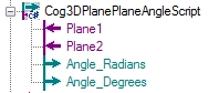
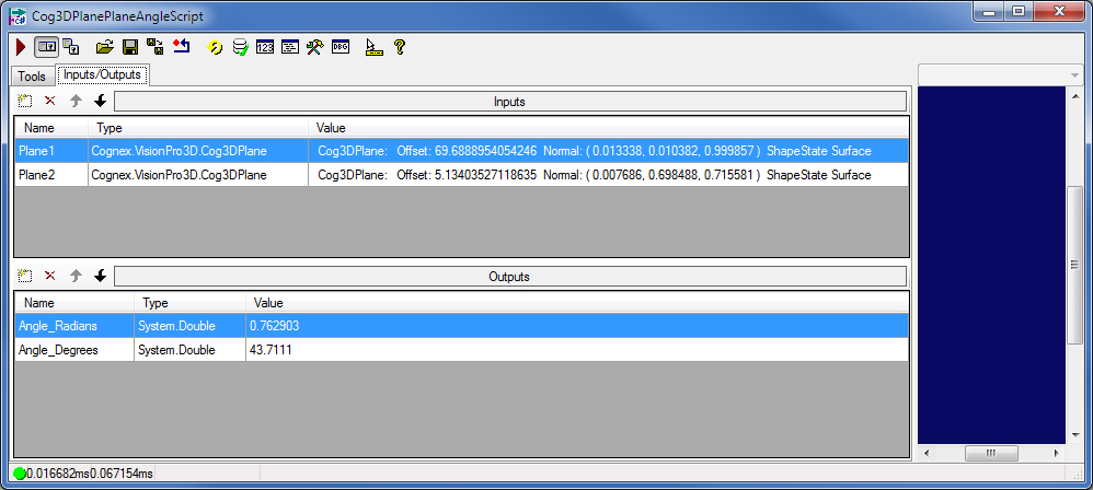
The Cog3DPlanePlaneAngleScript determines the angle of a plane relative to another one in the range image.
The tool returns the fitted plane as a Cog3DPlane object.
For the theory of range images, acquired from displacement sensors, see the Working with 3D Range Images topic. For information on setting up acquisition with your displacement sensor, see the Getting Started topic. For detailed information on range image acquisition, see the Acquiring Images from a DS900 Series Sensor and Acquiring Images from a DS1000 Series Sensor topics. For advanced range image acquisition details, including coordinate spaces related to range images, see the Range Image Coordinate Spaces and Associated Parameters topic. For hardware-related information (such as mounting and physical product features) and further product details, see the DS900 Quick Reference Guide, DS1000 Quick Reference Guide, and the DS1000 Technical Reference Manual.
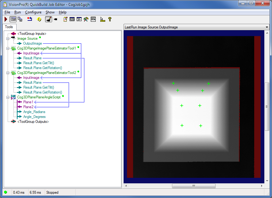
In QuickBuild, you can fit a plane on features in a range image as follows:
- Configure the Job's Image Source to acquire images from a Cognex 3D displacement sensor or from an image database containing range images.
-
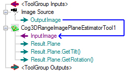
Add and connect a Cog3DRangeImagePlaneEstimatorTool to the Image Source.
-
Acquire a range image about the object that you want to inspect, open the tool, and make sure the plane that you want to measure is in your field of view on the display. Apply Colormap if necessary to better see the plane that you want to measure.
-
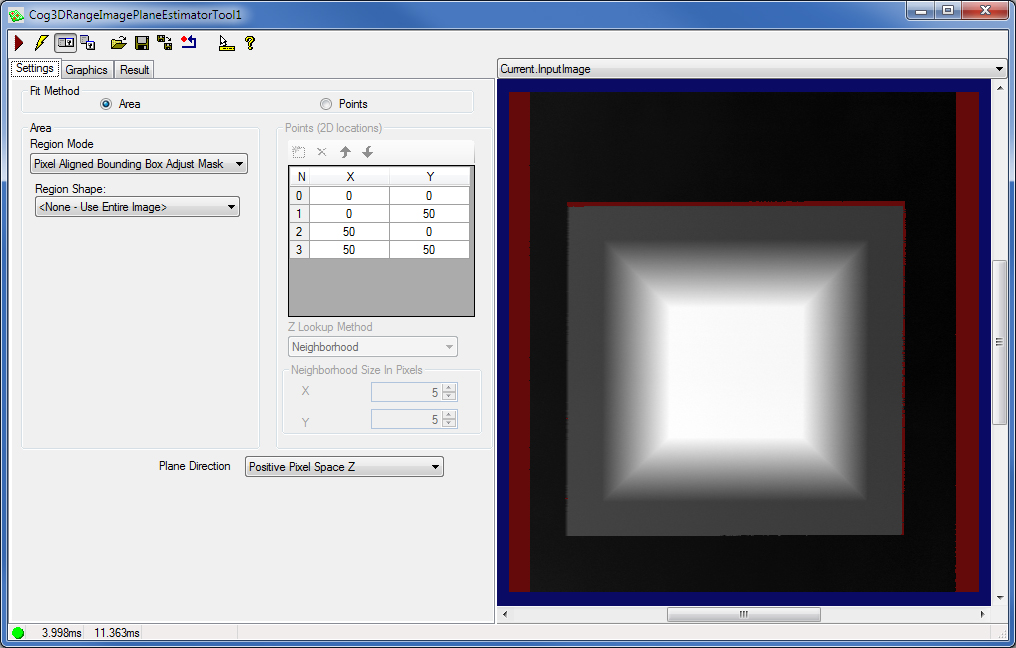
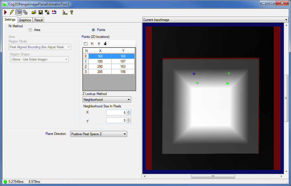
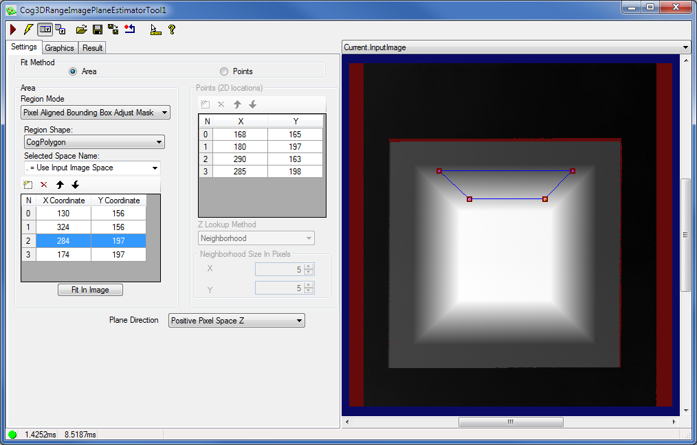
Choose the FitMethod, that is, whether you want to fit the plane based on a set of discrete points or an area.
Add as many points as you want to use in the Points (2D locations) box and specify the location for each. The more points (or the larger area) you use for plane fitting the more accurate the fitting will be (at the cost of increased running time). In this example, four discrete points are used.
Also, specify the ZLookupMethod, which defines for all points if the single pixel value at the x-y location of each point (Single Pixel mode) or the median pixel value of the rectangular neighborhood around that single pixel (Neighborhood Median mode) should be used to determine the height values (the z-coordinate) of the points, or all visible pixels (treated as single pixels) in the rectangular neighborhood should be used for the plane estimation (Neighborhood mode, the default). You can specify the neighborhood size as well. In this example, the default (Neighborhood) mode has been chosen with the default neighborhood size.
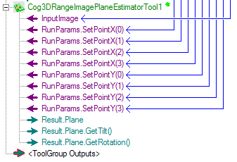
If the position of your object under inspection varies in the range image, you may use fixturing. Also, you can specify the points based on which plane fitting is performed as input parameters coming from other tools. To do this, right-click the tool in QuickBuild, select Add Terminals..., and select the SetPointX() and SetPointY() runtime parameters to specify the x and y coordinates of each point.
-
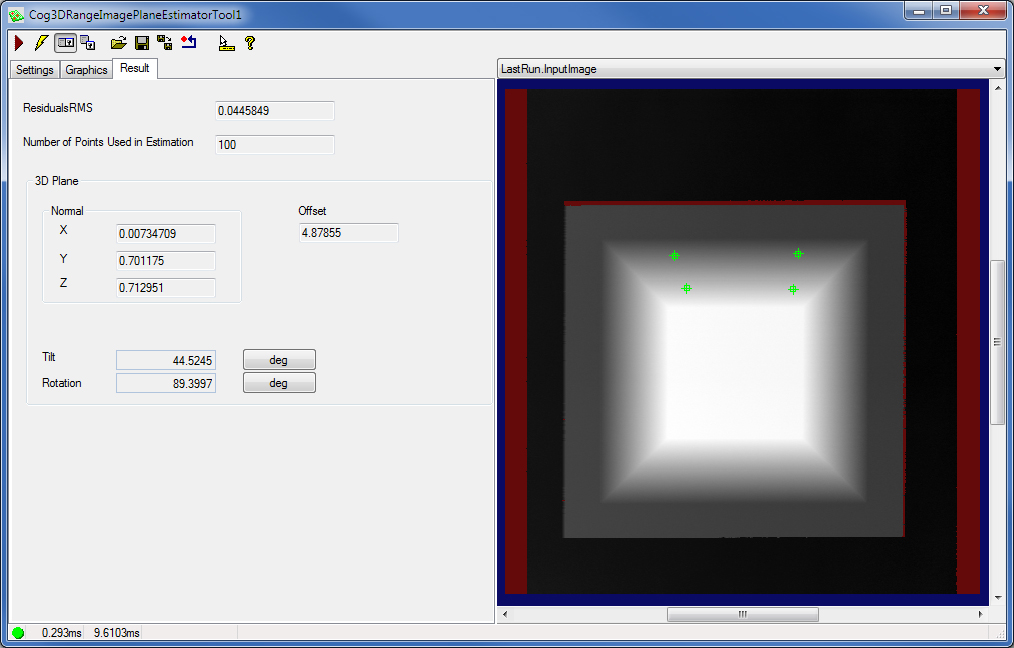
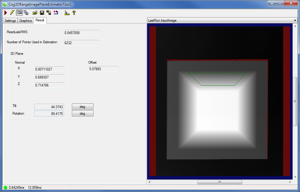
Run the tool and view the results on the Results tab.
The tool returns the fitted Plane by returning its Normal and Offset, you also GetTilt and GetRotation of the fitted plane. The tool in addition returns the ResidualsRMS error and the actual NumberOfPointsUsedInEstimation.
You can specify an input image mask that can be used by itself or with a region for plane estimation by right-clicking the tool in the job, selecting Add Terminals, and adding the input image mask from the RunParams group. You can also specify X and Y offsets for the mask the same way.
In the API, you can do the following to specify the input parameters based on which plane fitting is performed:
- Specify a set of points based on which plane fitting is performed. A minimum of 3 points must be provided in the selected space (pixel space) of the input range image.
- Instead of specifying discrete points, specify a region to define the pixels to be used in fitting the plane.
- In addition, specify an input image mask that can be used by itself or with a region.
You specify the RunParams, the Region, and the InputImage for the tool. Then run the tool for the Result to be created containing the fitting results.
You can specify the InputImageMask among the RunParams of the tool. You can shift the position of the mask by specifying the InputImageMaskOffsetX and InputImageMaskOffsetY parameters.If you want to determine the angle of a plane relative to another one in the range image, you can use the Cog3DPlanePlaneAngleScript from QuickBuild. A new Cog3DPlanePlaneAngleScript appears as shown in the following figure: