This topic contains the following sections.
The CogCalibCheckerboardTool is one of two calibration tools provided by VisionPro. For more information, see the related topic on Calibration and Fixturing and the overview of the tool.
The CogCalibCheckerboardTool works in either linear or nonlinear (with warping) mode. Both modes create a mathematical mapping between physical coordinates and the pixels of a given input image. In nonlinear mode, the tool measures, and then corrects, perspective and radial distortions.
When you use the N-point calibration tool or the Checkerboard calibration tool in linear mode to calibrate an image, the resulting calibration can only account for aspect ratio distortion (as well as any translation or rotation).
Note: The CogCalibCheckerboardTool supports the use of both checkerboard and grid-of-dots calibration plates. While either type of plate can be used to perform nonlinear calibration, using a checkerboard plate will produce a more accurate calibration than a grid-of-dots plate, particularly when nonlinear distortion is present. All of the examples, illustrations, and discussions in this topic show the use of a checkerboard calibration plate.
The Checkerboard Calibration tool can correct for distortion in the images your vision application acquires.
Images acquired using a camera and lens usually exhibit these types of distortion:
- Aspect ratio distortion caused by non-square pixels
- Planar perspective distortion caused by the camera being off-axis
- Radial distortion caused by the optics in the camera lens
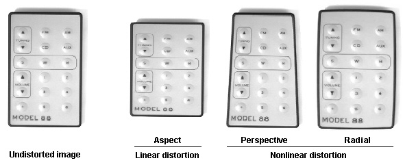
Note: The distortion shown in this figure (and others in this topic) is exaggerated. While the Checkerboard calibration tool can easily handle the degree of distortion shown in these illustrations, it is typically used to correct less distorted images.
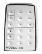
In most cases, the distortion present in an acquired image is a combination of the three types of distortion shown above:
The difference between two images caused by aspect ratio distortion is linear; it can be described by a system of linear equations and represented by a CogTransform2DLinear object. Perspective and radial distortion are both nonlinear. The difference between two images caused by these types of distortion cannot be represented by a system of linear equations.
Note: Nonlinear calibration cannot be used to calibrate images that have been stitched together from multiple acquisitions. Only images acquired using a single exposure exhibit the type of distortion that this tool can correct. Nonlinear calibration can be used to calibrate images from linescan cameras, but you must specify Linescan Camera Calibration explicitly.
When you use the Checkerboard calibration tool in nonlinear mode, the tool computes a mathematical representation of any perspective, radial, and aspect ratio distortion present in the calibration image. Because other VisionPro tools can only make use of linear transformations, the Checkerboard calibration tool does not attempt to add these nonlinear transformations to the run-time image's coordinate space tree. Instead, the tool warps the acquired image itself, so that the effect of the nonlinear distortion is removed.
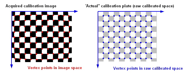
The following figure shows the effect of typical optical distortion on an acquired image of a checkerboard-style calibration plate:
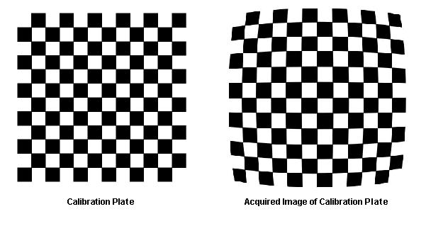
The Checkerboard calibration tool works by locating tile vertices in the supplied image. A tile vertex is the point where the corners of four tiles meet. Using tile vertices provides more accurate calibration results than using the centers of dots or other image features which can themselves become distorted.
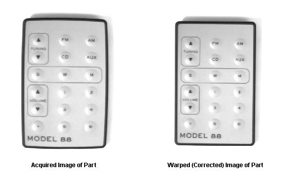
At calibration time, the tool computes the nonlinear transformation between the tile vertices in raw calibrated space (the real-world locations based on the tile size you specify and the plate origin) and the tile vertices located in the acquired image. At run time it uses this transformation to warp the pixels in the acquired run-time image to remove the distortion, as shown in the following figure:
In addition to warping the run-time image, the Checkerboard calibration tool also optionally constructs a CogTransform2DPerspectiveAndRadial object that represents the nonlinear transformation. While you should not add this transformation to a coordinate space tree, you can use it to map points between the selected space of the input image and raw calibrated space.
At calibration time, the Checkerboard calibration tool computes both the linear and nonlinear components (when the tool is in nonlinear mode) of the overall transformation of the vertices from raw calibrated space to the calibration image's selected space. Like the N-Point calibration tool, the Checkerboard calibration computes the RMS error of the computed transformation.
The tool also generates error strings that help you evaluate the size and possible cause of the computed error. In general, the most likely cause of excessive error is specifying linear mode calibration when the calibration image exhibits significant nonlinear distortion. Since the Checkerboard calibration tool automatically determines the correspondence between points in the two spaces (unlike the N-Point tool), high RMS error is unlikely to indicate a correspondence error. Instead, a high RMS error may indicate a failure to locate tile vertices correctly, or it may indicate the presence of distortion other than simple perspective and radial distortion.
The Checkerboard calibration tool lets you control how image warping is performed.
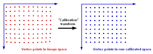
Like all calibration tools, the Checkerboard tool considers a set of points in an acquired image and the corresponding set of points measured in a calibrated space. The Checkerboard calibration tool obtains the first set of points by locating the vertices in an acquired image of a checkerboard calibration plate and the second set from the dimensions of the tiles in the real world (based on the actual tile size that you specify):
The tool computes the calibration transformation between these two sets of points. It is this transformation that it uses to warp run-time images.
In the case of the example shown in this section, the calibration image exhibits a form of radial distortion called "barrel distortion". The calibration transformation required to map the acquired pixel space to the raw calibrated space has the effect of pulling the points in the corners of the image outward. The following figure shows a magnified view of the upper-left corner of the image. The blue arrows represent the movement required to transform the pixel space points (red) to their corresponding raw calibrated points (blue).
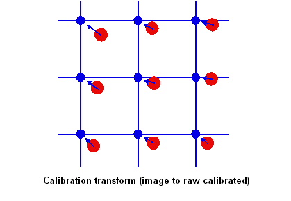
The tool uses this calibration transformation to warp the run-time image to remove the distortion detected during calibration.
When the Checkerboard calibration tool warps a run-time image, it takes steps to make sure that all of the information present in the acquired run-time image is also present in the warped image. It does this by performing the image warping in the following steps.
- It transforms the bounding rectangle of the acquired image using the calibration transformation computed during the Calibration phase. The result of this transformation is a non-rectangular shape.
- It computes the bounding rectangle that encloses the transformed shape. This becomes the bounds of the destination image.
- It transforms the center points of each pixel in the destination image (computed in the previous step) to the corresponding point in the run-time image.
- The tool samples the run-time image at each of these sampling points to compute the pixel values in the warped image.
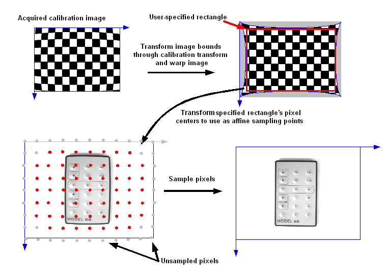
The following figure shows the image warping process:
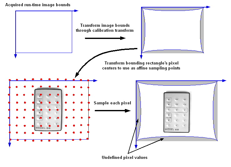
Note that as a result of this process, certain pixels in the warped image are undefined or unfilled. That is, there was no corresponding location in the run-time image from which to sample pixels. By default, the tool simply fills these values with an arbitrary pixel value (128), and it also provides you with a mask image that corresponds to these pixels.
Alternatively, the tool lets you specify a destination rectangle for the warping process. This lets you prevent the creation of any regions of undefined pixel values, at the cost of discarding parts of the acquired run-time image. You can specify this rectangle using a warped version of the original calibration image, making it easy to select the correct part of the image, as shown in the following figure:
Regardless of how you generate the warped image, be aware VisionPro does not support images that contain more than 32767 rows or 32767 columns of pixels. Since the warped image size depends on the degree of warping in the calibration image, you might need to experiment with the maximum calibration image size that will not produce a warped image that exceeds 32767 in row or column size.
As described in the previous section, each pixel in the warped image is generated by sampling the pixel values at the corresponding point in the acquired run-time image. In most cases, the location of a sampling point can be extrapolated from the locations of nearby sampling points. The tool reduces the amount of time and memory required for image warping by extrapolating the locations of some of the sampling points (because the process of mapping a point through a nonlinear transformation is time-consuming).
You can control the amount of extrapolation done by the tool by changing the value of the WarpMaxErrorInPixels property. The tool will extrapolate sampling locations until the difference between the extrapolated and the actual sampling location exceeds the error you specify. Then the tool transforms a pair of points explicitly and resumes extrapolation.
In most cases, you should specify a very small value for this error. The default value for this property is 0.01 pixels. The effect of changing the value of this property on the speed of image warping is very dependent on the degree of radial distortion present in the image. If the image has very little distortion, then changing this property will have little or no effect on warping speed. If the image is heavily distorted, then increasing the value of this property can greatly reduce the amount of time required for warping.
Note: The maximum warping error is not related to the ComputedRMSError property. The computed RMS error, which is measured in uncalibrated space, is a measure that the tool computes to measure how accurately the computed transformation represents the difference between the uncalibrated and raw calibrated vertex points. The maximum warping error is a value that you specify to adjust the accuracy with which the image warping represents the computed transformation.
The Checkerboard calibration tool lets you specify a scale and rotation value to apply during the warping operation. Because the tool is already sampling each pixel in the input image to create the warped image, the added cost of introducing a scale or rotation is negligible. If your application requires that the acquired image be scaled or rotated, you can increase your application's overall speed by performing that step as part of the image warping operation.
As part of the run-time warping operation, the tool always produces an output image oriented to the standard image coordinate system. If you acquired your calibration image with the plate at an angle, the warped output image will have this angle removed, as shown in the following figure:

You can also use the warp rotation property to compensate for this rotation.
As described in the overview of calibration, the physical and optical configuration you use to acquire the calibration image must be identical to the configuration you use to acquire the run-time image. Additionally, any post-acquisition image processing must be applied identically to both the calibration and run-time images.
The Checkerboard calibration tool performs a check at run-time to verify that the second requirement is met. It performs this check by verifying that the mapping from the selected space of the run-time image to that image's pixel space (# space) is identical to the corresponding mapping in the calibration image.
There is one case in which the Checkerboard calibration tool can still operate correctly if these two transformations are not the same. If the run-time image has undergone a whole-pixel shift, and if this shift is recorded in the root-to-pixel transformation within the image's space tree (@ space to # space), then the Checkerboard calibration tool will work correctly.
This type of whole-pixel shift can be introduced by certain image processing operations and by acquiring images from a line-scan or digital camera using a smaller region of interest (ROI) than was used to acquire the calibration image.
Note: The run-time image can be smaller than the calibration image only if you have specified a WarpDestinationRectangle. In all cases, the run-time image must contain enough pixels to compute values for all pixels in the output image.