To use the CogCalibCheckerboardTool to perform linear or nonlinear calibration, you must supply the tool with an acquired image of a calibration plate. The tool supports both checkerboard and grid-of-dots plates. Each type of plate must meet specific requirements in order to work with the tool.
Note: Cognex recommends the use of a checkerboard plate. Calibration using a checkerboard plate and exhaustive feature extraction provides a more accurate calibration than using a grid-of-dots plate.
This topic contains the following sections.
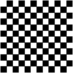
The Checkerboard calibration tool can only be used with a checkerboard-style calibration plate that meets specific dimensional requirements:
- The black and white tiles must be arranged in an alternating pattern.
- The black and white tiles must be the same size.
- The tiles should be square, or if they are not square, their aspect ratio should be within the range 0.90 through 1.10.
The following figure shows an example of a checkerboard calibration plate:
You can obtain checkerboard calibration plates that meet the requirements listed in this topic from Cognex Corporation, or you can manufacture your own plate. Keep in mind that the accuracy of the calibration you obtain depends on the precision of the manufactured plate.
In addition to the requirements for the design of the calibration plate, there are also specific requirements for the acquired image of the plate:
- The acquired image must include at least 9 full tiles.
- The tiles in the acquired image must be at least 15x15 pixels in size.
If the acquired image does not meet these requirements, the tool may not operate correctly.
In general, increasing the number of tiles visible in the calibration image (by reducing the size of the tiles on the calibration plate), improves the accuracy of the calibration, although the improvements are smaller the greater the number of tiles that are present. In most cases, since the only negative effect of increasing the number of tiles is that it takes longer to compute the calibration, you should size your tiles so that there are several hundred tiles visible in the image.
Also, since accuracy improves when the vertex points are spread evenly across the entire image, make sure that the calibration image is completely filled with tiles, as shown in the following figure:
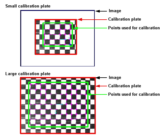
Note: If you are only interested in measuring objects or positions in part of the input image, you should only include tiles that cover that part of the image. Attempting to correct distortion in parts of the image that are not of interest to your application can reduce the accuracy of the calibration in the parts of the image that you are interested in, and can slow your application.
By default, the Checkerboard calibration tool uses a Cognex-defined fiducial mark in the input image to establish the origin of raw calibrated space. The requirements for the fiducial mark are listed below:
Note: All Cognex-supplied calibration plates include the fiducial mark.
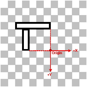
- The mark must be made of two bars, one 1x5 tiles in size, the other 1x3 tiles in size.
- The short edge of the short bar must touch the long edge of the long bar one tile from the end of the long bar.
- Each bar must be white with a black border one quarter tile thick.
- The bars must be arranged as follows with respect to the polarity of the tiles on the plate: the long bar must lie between two white tiles and the end of the short bar must be adjacent to a white tile.
- The origin is defined as the intersection of two lines drawn perpendicular to the ends of the two bars furthest from their intersection point.
- The positive x-axis is aligned with the long bar in the direction from the bars' intersection to the end of the long bar.
- The positive y-axis is aligned with the short bar in the direction from the bars' intersection to the end of the short bar.
The following figure illustrates the requirements for this fiducial mark (black tiles are shown in grey to help illustrate the fiducial mark):
Keep in mind that the origin specified by the calibration plate origin is for raw calibrated space. You specify the final orientation, handedness, and origin of calibrated space by supplying an optional rigid origin adjustment.
Note: If you supply a calibration image where the fiducial mark indicates a right-handed coordinate space, the tool will swap the handedness of both the calibration and the run-time image during warping. The tool always assumes that the raw calibrated coordinate space is a rotated left-handed coordinate space.
In addition to the simple 'L'-shaped origin fiducial mark described above, the CogCalibCheckerboardTool also supports checkerboard calibration plates with multiple DataMatrix code fiducial marks. These plates use DataMatrix codes to label the locations multiple grid vertices on the plate as well as the plate's grid pitch (the distance between successive corresponding points or lines). The following figure shows how multiple DataMatrix fiducial marks serve to label four vertices on a checkerboard calibration plate (in this case, a plate with a 2mm grid pitch):
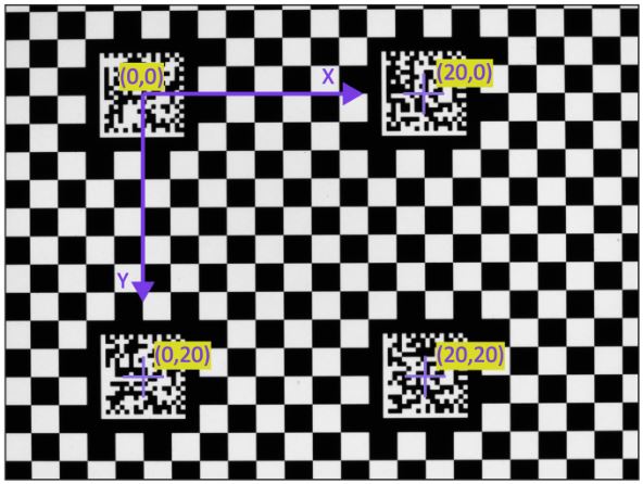
| All Cognex-supplied DataMatrix plates encode the grid pitch; plates that you construct using Cognex-supplied CAD data may not include the grid pitch. |
The handedness and orientation of the plate coordinate space are defined by the orientation of the DataMatrix mark, as shown below. The postive X- and Y-axis directions are established by the orientation of the finder pattern.
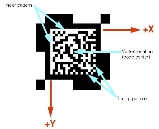
If the plate is mirrored (as would be the case if a transparent plate were viewed from behind), the calibration tool detects that the DataMatrix symbol is mirrored, and inverts the handedness of the coordinate system.
Checkerboard calibration plates with DataMatrix fiducial marks provide several important advantages:
- The plates enable the use of the CheckerboardExhaustiveMultiRegion mode in standard 2D camera calibration. This permits calibration in cases where reflections or other occlusions hide regions of plate vertices. Using this mode, the calibration tool can make use of multiple regions of vertices, as long as each region contains at least one fiducial mark.
- The plates enable the use of the ExhaustiveMultiRegion mode in 3D camera calibration. This greatly improves the accuracy and robustness of 3D calibration.
- The plates make it possible to use the CogHandEyeCalibrator with multiple cameras with non-overlapping fields of view, as long as each camera can see at least one fiducial mark from the same plate at the same time.
| Cognex does not publish the specific encoding used for DataMatrix fiducial marks. Cognex can provide high-accuracy DataMatrix fiducial plates in a wide range of sizes, grid pitches, and materials. Contact your Cognex representative for more information. |
As you configure a Checkerboard Calibration tool you must choose a mode for extracting the features of your calibration plate. The tool supports the following modes for older VisionPro applications that use either a checkerboard or grid-of-dots plate:
- Checkerboard
- DotGrid
Cognex does not recommend using either the Checkerboard or DotGrid modes for new vision applications. Instead VisionPro offers the following exhaustive or efficient feature extraction modes:
- CheckerboardExhaustive for plates with or without the "L" fiducial or CheckerboardExhaustiveMultiRegion for plates with DataMatrix fiducial marks.
- CheckerboardEfficient for plates with or without the "L" fiducial or CheckerboardEfficientMultiRegion for plates with DataMatrix fiducial marks.
In general, the efficient modes will execute faster than the exhaustive modes with the following exceptions and limitations:
- The number of features extracted in the efficient modes might be lower than the number of features extracted in the exhaustive modes.
- The accuracy of the features extracted in the efficient modes might be lower than the accuracy of the features extracted in the exhaustive modes. This is more likely to be true when the quality of the calibration image is poor (e.g. highly distorted, and/or low resolution, and/or poor contrast).
- When lower accuracy features are extracted, the process of computing a nonlinear calibration might take longer. The nonlinear calibration algorithm does more work to produce minimal error results from less accurate features. Because of this, when the calibration image is of poor quality, overall calibration time using efficient feature extraction may actually exceed overall calibration time using exhaustive feature extraction, and the overall quality of the calibration (as indicated by the RMS Error) might be lower.
You might need to experiment with the efficient and exhaustive modes to see which works best with your application. See the topic Checkerboard Calibration Tool Edit Control for details on choosing a feature extraction mode.
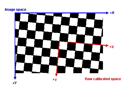
If you specify to the tool that no fiducial mark is present in the calibration image, the tool assigns the origin of raw calibrated space to be the vertex closest to the center of the calibration image. The x-axis is aligned to the vertex grid axis that is closest in angle to the x-axis of the calibration image's image coordinate space. The y-axis is aligned to the vertex grid axis that is closest in angle to the y-axis of the calibration image's image coordinate space.
The following figure shows how the tool assigns the default origin:
Note: Cognex recommends the use of checkerboard calibration plates with the CogCalibCheckerboardTool. Support for grid-of-dots plates is provided for compatibility purposes.
The Checkerboard calibration tool can be used with grid-of-dots calibration plates that meet the following specification.
- The plate must contain a regular grid of round dots.
- The rows and colums of dots must be at right angles to each other.
- Both black dots on a white background and white grids on a black background are supported, as long as the difference in grey levels between dots an the background exceeds 8% (20 grey levels in an 8-bit image).
- The dots must be the same size. A single dot may be up to 50% smaller or larger than the average dot size.
- The dot spacing in the X-direction must differ from the Y-direction spacing by no more than 10%.
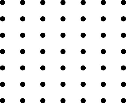
The following figure shows an example of a grid-of-dots calibration plate:
In addition to the requirements for the design of the calibration plate, there are also specific requirements for the acquired image of the plate:
- The dots must be between 10 and 40 pixels in diameter.
- The grid must contain no less than 16 and no more than 2000 dots.
- There must be at least 8 pixels between dot centers.
- The center-to-center distance between any two adjacent dots in any row or column may not exceed 512 pixels for plates with fiducial marks or 1024 pixels for plates without fiducial marks.
- No dot may be closer than one-half the diameter of a dot to the edge of the image (there must be a quiet zone containing no dots around the image edge, and this quiet zone must be at least half as wide as a dot).
- The optical axis of the camera used to acquire the image must be within 30 degrees of perpendicular to the plate. Note that this requirement does not exist for checkerboard plates.
If the acquired image does not meet these requirements, the tool may not operate correctly.
In general, the greater the number of visible dots within the image, provided that the image and plate meet the listed requirements, the more accurate the calibration will be.
As is the case with checkerboard plates, the tool supports the use of fiducial marks on grid-of-dots plates to define the plate origin and handedness. The tool also supports the use of fiducial marks to indicate the dot spacing.
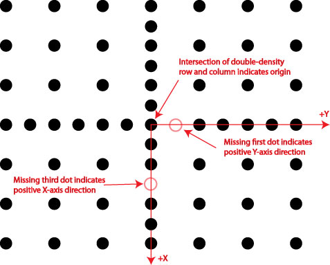
If the plate includes a single row and colum of dots where the dots appear at twice the normal density, the tool will use the center of the dot that lies at the intersection of the double-density row and column as the plate origin. If the plate includes this double-density row and column, then it must also include a pair of mark spaces (missing dots) to indicate the identity of the x-axis and y-axis and to specify the handedness of the coordinate system. A mark space at the first position from the intersection of the double-density row and column indicates the positive Y-axis while a mark space at the third position indicates the positive X-axis.
The following figure illustrates the use of these fiducial marks:
Note: If the plate includes these fiducials, they must meet the following requirements:
- One row and one column of double-density dots must be present.
- The mark spaces at position 1 and 3 must be present.
Note: Grid-of-dots plates supplied by Cognex that include these fiducials specify a right-handed coordinate space, while Cognex-supplied checkerboard plates specify a left-handed coordinate space.
If you specify to the tool that no fiducial mark is present in the calibration image, the tool assigns the origin of raw calibrated space to be the dot center that is closest to the center of the calibration image. The x-axis is aligned to the grid axis that is closest in angle to the x-axis of the calibration image's image coordinate space. The y-axis is aligned to the grid axis that is closest in angle to the y-axis of the calibration image's image coordinate space.
Note: When you configure the CogCalibCheckerboardTool, you must specify whether the plate image includes a fiducial or not. If you attempt to calibrate a plate with a fiducial mark without specifying the presence of the mark, or if you attempt to calibrate a plate without a mark but you specify the presence of a mark, the tool will not compute a valid calibration.
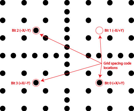
In addition to specifying the origin, orientation, and handedness of the coordinate space, you can also use a set of specially-located extra dots on a grid-of-dots plate to specify the dot spacing. The tool defines four special locations, one in each quadrant of the plate, that define the plate's dot spacing. Each location may either be blank or have a dot. The four locations together are used to compose a 4-bit value.
The four bit positions are defined as follows:
- Bit 0: In the +X/+Y quadrant located with an X-position between the first and second grid dot in the +X direction and a Y-position between the first and second grid dot in the +Y direction.
- Bit 1: In the -X/+Y quadrant located with an X-position between the first and second grid dot in the -X direction and a Y-position between the first and second grid dot in the +Y direction.
- Bit 2: In the -X/-Y quadrant located with an X-position between the first and second grid dot in the -X direction and a Y-position between the first and second grid dot in the -Y direction.
- Bit 3: In the +X/-Y quadrant located with an X-position between the first and second grid dot in the +X direction and a Y-position between the first and second grid dot in the -Y direction.
For a plate with a right-handed coordinate system (the default for Cognex-supplied grid-of-dots plates), the bits are arranged in the counter-clockwise direction, as shown in the following figure:
The possible grid spacing values that can be expressed using this scheme are listed below:
| Value | Description |
| 0 | No dots: grid pitch specified by user |
| 1 | 20 millimeters |
| 2 | 10 millimeters |
| 3 | 5 millimeters |
| 4 | 2 millimeters |
| 5 | 1 millimeter |
| 6 | 50 millimeters |
| 7 | 100 millimeters |
| 8 | 1.0 inch |
| 9 | 0.5 inches |
| 10 | 0.25 inches |
| 11 | 0.125 inches |
| 12 | 0.1 inches |
| 13 | 2.0 inches |
| 14 | 4.0 inches |
| 15 | 12.0 inches |
The spacing defined in the example shown above is 2.0 inches (1101 =13).
Note: If the tool detects these marks, it will overwrite any grid spacing value that you have entered or specified manually.