This topic contains the following sections.
The topic Using QuickBuild describes how to use QuickBuild to create and test a complete vision application. For each Job that you add to a QuickBuild application, you must configure how it will acquire the images it will analyze.
A new QuickBuild application contains one Job by default, as shown in the following figure:
Double-click on the Job to open it in a Job Editor, as shown:
You must set the acquisition properties of a Job before you can use it to acquire images. Choose Configure->Image Source from the Job Editor or click:

from the button bar. The Image Source dialog box appears as shown in the following figure:
To acquire images from a file or a directory of image files instead of a connected camera, click the Image database button in the Image Source dialog box. This option is selected by default. You can acquire images from any of the following sources:
- A file storing a single image
- An image-database file storing multiple images
- A directory of files containing both single images and image-database files
QuickBuild supports the following file formats:
- Bitmap (*.bmp)
- Tagged image file (*.tif)
- JPEG (*.jpg)
- Portable Networks Graphic (*.png)
- Image database (*.idb)
Cognex database (*.cdb)
You can use the Cognex IDB Editor to create image-database files or Cognex-database files.
The text box along the top allows you to type in the name of the file directly and accepts environment variables, valid UNC syntax, and relative path names based on the current working directory. The text box changes color as you enter a filename, turning pink if its contents do not point to a valid path and blue while the path is valid.
The following figure shows the Image Source dialog box configured to acquire images from the file Caliper_Counter_Demo.idb, stored in the \Images subdirectory of your VisionPro installation.
The Acquisition rate lets you specify how many images QuickBuild will acquire each second. Modifying this value can help you simulate a maximum frame rate for your application. Be aware that other factors, such as the load on your computer and whether the image database is on a network could result in a frame rate below the rate you specify.
The Thumbnail preview lets you view the images to be acquired from files as thumbnails. You can also use this to specify on which images the Job should be run.
For more information, see the topic Acquiring Images from a File or Directory.
This section contains the following subsections.
- Settings Tab
- Strobe and Trigger Tab
- Image Properties Tab
- Lookup Table Tab
- Firewire Tab
- GigE Tab
- Imaging Device Tab
- Line Scan Tab
- Custom Properties Tab
Use the following procedure to configure the Image Source dialog box to acquire images from a connected camera:
- Click the Camera button in the Image Source dialog box.
Use the Image Acquisition Device/Frame Grabber list to select the image acquisition device for this Job. VisionPro supports the following types of acquisition devices:
- A Cognex frame grabber
- A GigE Vision camera
- A third-party acquisition adapter
- A Cognex DS1000 series sensor
For example, the following figure shows the device listing when the PC contains a CIC GigE camera:
Use the Video Formats list to select a video format based on the camera you will use to acquire images for this Job. The list varies depending on the acquisition device you are using. For example, the following figure shows the video formats listed for the CIC GigE camera:
- Use the Camera Port list, if necessary to select which segment of the breakout cable connects to this camera.
Click Initialize Acquisition.
QuickBuild attempts to create a first-in-first-out (FIFO) acquisition queue for this Job. If successful, the Image Source dialog box displays additional tabs. For example, the following figure shows part of an Image Source dialog box initialized to acquire images with a CIC GigE camera:
Use the additional tabs of the Image Source dialog box to set other image acquisition properties as needed for your vision application.
For information on setting up acquisition with your DS1000 series sensor quickly, see the Getting Started with the DS1000 topic. For detailed information on acquiring from a DS1000 series sensor, see the topic Acquiring Images from a DS1000 Series Sensor.
The values in the Settings tab vary depending on the particular image source you are using. You may or may not see all the parameters shown in the following figure:
| Property | Description |
| Exposure | Choose an exposure time. The special value 0.00 instructs QuickBuild to use the shortest time that the camera supports. The Image Source dialog box, however, may not let you specify a setting of 0.00 depending on the acquisition device you are using. |
| Brightness | Set the brightness level for each image acquisition. You might need to experiment with different values in order to determine the best level for your application. |
| Contrast | Set the contrast level for each image acquisition. You might need to experiment with different values in order to determine the best level for your application. |
| Timeout | Set a timeout period that determines how long the acquisition device waits for an image to become available before the Job generates a timeout error. The corresponding API for the Timeout value varies depending on the frame grabber you are currently using. |
| UGain | Available only with color cameras, increasing this value causes the acquired images to reflect more red or 'warmer' tones. |
| VGain | Available only with color cameras, increasing this value causes the acquired images to reflect more blue or 'cooler' tones. |
| AutoWhiteBalance | Available only with color cameras, sets the correct white balance automatically if the camera supports it. |
Use the Strobe and Trigger tab to control an optional strobe light as well as to configure the type of trigger this acquisition channel uses to signal that an image acquisition should begin. The fields in this tab vary depending on the specific frame grabber you use. The following figure shows an example Strobe and Trigger tab:
Configure the following settings on the Strobe and Trigger tab:
| Property | Description |
Enables the strobe light for each image acquisition. With a strobe light enabled, configure the following settings:
| |
Choose one of the following incoming trigger type for this Job:
| |
| Sets or gets the minimum trigger width in milliseconds. The trigger input signal must be asserted for at least this amount of time before it is recognized as a valid input trigger. QuickBuild ignores any trigger signal that does not meet this width constraint. | |
Sets the minimum time between triggers in milliseconds. Only the first valid trigger within a period will initiate a camera integration cycle. Other valid triggers in that same period are missed. You can use this value to help limit the camera acquisition rate. Legal values range from 0 to 65.5. Zero specifies that there is no period requirement. | |
| Sets the period of time, in milliseconds, between the receipt of the acquisition trigger and the start of camera integration. | |
| Available only on the MVS-8602e and MVS-8602e PoCL, allows your application to ignore any missed triggers and avoid the processing time required to handle an acquisition failure. |
This section contains the following subsections.
By default, most cameras capture the entire image available, but you can specify a region of interest within the specific section of the total image available. Specifying a region of interest can increase the speed at which the application operates. In addition, the length of the image a line scan camera can capture is variable and is determined by the height of the region of interest. For this reason, applications using a line scan camera always specify a region of interest.
The following figure shows an example Image Properties tab:
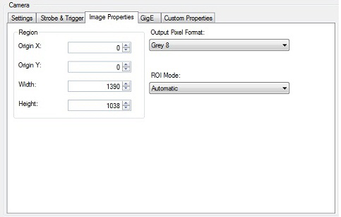
ROI Mode (Region of Interest) allows you to choose between Automatic and Manual mode:
| Automatic | Automatic mode will adjust the region of interest to meet the limitations of the hardware, and then apply a pel buffer sub-window to produce the actual region of interest requested. For example, if the width is not adjustable on the camera while the height is, Automatic mode will use the hardware setting to set the height and then set a pixel buffer sub window for the requested width. |
Manual | Manual mode should only be used if a corect image cannot be acquired with Automatic mode. This will primarily be with cameras where the image size is determined by something other than ROI settings. For example, a linescan camera that is being used in a mode where the camera acquires lines while a trigger signal is high, resulting in a variable-length image . In Manual mode, ROI settings are written without modification to hardware, providing the corresponding setting is writable. If the setting violates a hardware limit or modulo requirement, the results are undefined. Some cameras will not produce an error, but will not acquire an image while the settings are invalid. In Manual mode, the acquired image is whatever is sent back from the camera (no sub-window is applied). This may be larger or smaller than the settings for the region of interest, depending on how the camera works. The primary benefit of Manual mode is for use with camera whose image size determined by something other than the settings for the region of interest. |
Region
Use the fields in the tab to specify the origin, width, and height of the region of interest.
Output Pixel Format
Use the Output Pixel Format list to choose one of the following pixel formats for the images the Image Source makes available to the vision tools you add to QuickBuild:
| Property | Description |
| CogImage8Grey | Grey scale images that offer 256 possible shades of grey from black to white. |
| CogImage16Grey | Grey scale images that offer 16-bit encoding. See the topic Working with 16-Bit Images for more information. A 16-bit greyscale image supports 65,536 grey values, but you must be using a 16-bit capable camera in order to produce images that exhibit this larger range. Choosing Grey 16 when you are using an 8-bit greyscale or 24-bit RGB camera produces images that are stored using the CogImage16Grey class but support only 256 possible grey values. |
| CogImage24PlanarColor | An image that uses 3 coincident arrays of 8-bit pixel values to represent shades of red, green and blue. Use this option with a supported color camera to generate color images for your vision application. If you select this option with a grey scale camera, the output images use the CogImage24PlanarColor class with the values for red, green, and blue in each array set to identical values to generate a corresponding grey pixel value. |
| Automatic | Allows QuickBuild to generate images with the appropriate output pixel format based on the type of camera you are using and the video format you chose on the Settings tab. |
Image Pool Size
If you are using an MVS-8600 series frame grabber, you can use the settings on the Image Properties tab to specify the size of the image pool the frame grabber will generate:
| Setting | Description |
| RecommendedHardwareImagePool | When selected, the image pool will automatically be sized to the recommended value. Be aware that the recommended value might change as the region of interest changes. |
| UseCustomHardwareImagePool | When selected, you can set the image pool to a specific value. Normally, you would only use a custom value if the recommended value causes a problem, which can occur if you are acquiring very large images and the recommended setting requires too much memory. |
| HardwareImagePool | Set the number of images in the pool. A larger value provides more reliable acquisition, but uses more memory. You will only be able to set the value if Use Custom Value is checked. |
An individual pixel in a grey-scale image can have a grey value ranging from 0 through 255. As QuickBuild captures an image, it can remap the grey value of any pixel to a different grey value through the use of a lookup table.
A lookup table is a 256-element array corresponding to the pixel values 0 through 255, where array element [0] corresponds to grey value 0, element [1] corresponds to grey value 1, and so on until element [255] which corresponds to grey value 255.
An acquisition channel using a lookup table evaluates each pixel in the image buffer and changes the grey value based upon the value for the corresponding element in the array. For example, if table element [50] has the value 75, any pixel with a grey value of 50 is given the new grey value of 75 before the image is made available for analysis by any other vision tool.
QuickBuild actually uses a lookup table regardless of whether you have set explicit values for the elements in the array. By default, however, it uses an identity lookup table, which does not change the grey values in the image. In an identity lookup table, element [0] is set to 0, element [1] is set to 1, and so on.
If your acquisition device supports a Lookup Table tab, you can redefine the values in the lookup table. For example, you might generate a new lookup table and choose a specific grey value as the midpoint between light and dark features in an image, and then map all darker pixels to some low value and all lighter values to some high value. This essentially binarizes each acquired image so that all features appear as either black or white.
The following figure shows the default Lookup Table tab:
Click inside the Value cell to change the value of any incoming grey value. Click Invert to swap dark values for light value and light values for dark values. Click Reset to set all values to their identity defaults.
Use the FireWire tab to view basic information about the connected FireWire camera, and allow the user to change camera bandwidth properties as well as give the user the ability to read and write to 1394 DCAM registers. The following figure shows an example FireWire tab:
The tab displays the following information regarding the camera:
| Information | Description |
| VendorID | The vendor for this camera |
| Camera Model | The camera model |
| AdapterLocation | The adapter location string of the host controller. |
| NodeNumber | The 6-bit node number that identifies this camera |
| Serial Number | The 10-bit bus number that identifies the 1394 bus to which this camera is connected. |
Use the following to control register access and bandwidth allocation:
| Control | Description |
| SetRegisterAccess | Write to the 1394DCAM register with the given address. |
| Value | The 32-bit value to write to the register at the given address. |
Lets you limit the amount of bandwidth used by an individual IEEE 1394 DCAM camera. You can connect more than one IEEE 1394 DCAM to a single IEEE 1394 adapter. By using this class, you can limit the amount of bandwidth used by individual cameras. Values range from 0.0, which directs the camera to consume as little bandwidth as possible, to 1.0, which directs the camera not to restrict its use of bandwidth. |
Use the GigE tab to view basic information about the connected GigE Vision camera and modify various GigE Vision properties. Refer to the GigE Vision Cameras User's Guide for more information. The following figure shows an example GigE tab:
The Camera Information section of the tab presents basic information regarding the camera and adapter you are using. Use the Feature Access area to examine and modify the XML-defined properties for the GigE Vision camera you are using.
- Enter the XML node name in the Feature field.
- Clicking Read (GetFeature) will read the value of the node and update the Value field.
- Clicking Write (SetFeature) will attempt to write whatever value is in the Value field to the node.
- Clicking Execute (ExecuteCommand) will attempt to execute the command feature specified in the Feature field.
Use the following parameters to set image transfer parameters:
- Use TransportTimeout to set a timeout, in milliseconds, for the camera to transmit an image. Cognex recommends using a larger value for cameras with a longer readout time, such as linescan cameras.
- Use LatencyLevel to set a latency level, where the default value of 3 generates low CPU load at the expense of some reliability. A value of 0 gives more reliable acquisition with less latency at the expense of higher CPU usage.
- Use PacketSize to set the size of image packets. The value that appears on the GigE tab is determined automatically based on the camera and the network configuration. In most cases, the value should not be changed and should be set to a value of 8000 or larger. A smaller value may indicate that jumbo frames are disabled on the network adapter, or that a switch in the network does not support jumbo frames.
QuickBuild will display a dialog box for any errors that occur, such an invalid entry for the Feature or Value fields. Refer to the documentation for the GigE Vision camera you are using for a list of supported XML nodes.
Use the Imaging Device tab to view information about the imaging device VisionPro can use to acquire images through an acquisition adapter supplied by a third party frame grabber or camera. The following figure shows a sample Imaging Device tab:
Use the Feature Access area to examine and modify the properties for the acquisition module as defined by the adapter you are using.
- Enter the property name in the Feature field.
- Clicking GetFeature will read the value of the node and update the Value field.
- Clicking [M:Cognex.VisionPro.ICogImagingDeviceAccess.SetFeature(System.String, System.String)] will attempt to write whatever value is in the Value field to the node.
- Clicking ExecuteCommand will attempt to execute the command feature specified in the Feature field.
Refer to the documentation for the acquisition adapter you are using for a list of supported properties.
This section contains the following subsections.
Use the Line Scan tab to provide QuickBuild with details about the encoder you use to keep track of an object as it travels past the line scan camera. Refer to the documentation for the encoder you choose for more information about any particular setting. The following figure shows the default Line Scan tab:
Encoder Settings
Use the following features to configure the encoder you use with your line scan camera:
| Feature | Description |
| SetStepsPerLine | Set the number of encoder steps for each image line. See the topic How To Set Steps Per Line For Line Scan Cameras for more information. |
| EncoderResolution | Controls the number of edges required for each encoder count |
| AcquireDirectionPositive | Indicates whether encoder values increase (checked) or decrease (unchecked) during an image acquisition. |
| StartAcqOnEncoderCount | Sets the number of encoder counts to wait before acquisition starts. |
| UseSingleChannel | Sets whether only one channel of the encoder signal is used for acquisition. |
| IgnoreBackwardsMotionBetweenAcquires | When enabled, any backwards motion after an acquisition will not delay the start of the next acquisition. |
Encoder Counter
As you test and debug your vision application, you might want to query the encoder counter at periodic intervals. Use the following fields to view statistics about the current encoder count:
| Feature | Description |
| Update Dynamically | Enable the display of the encoder count. |
| Update Interval | Specify how often the Image Source dialog box should sample the encoder for the current count. Be aware that updating the counter does impact the overall performance of the acquisition rate, an impact which increases as you lower the value of the update interval. |
| ResetCounter | Reset the current encoder count. |
| CurrentEncoderCount | The Image Source dialog box displays the current encoder count. |
Test Encoder
| Feature | Description |
| TestEncoderEnabled | Have the VisionPro software simulate the signals sent from an encoder as you test and troubleshoot the application. |
| IgnoreTooFastEncoder | Disables an acquisition failure due to a line overrun situation. |
Use the Custom Properties tab to control device-specific features of a GigE Vision camera or third-party imaging device. The Image Source dialog box only displays the Custom Properties tab if you are using a GigE Vision camera or an imaging device.
By default, the tab appears empty as shown:
Use the buttons within the tab:
To add, remove, reorder, remove and view custom properties for this image source. Selecting the Add button displays a list of custom property categories, as shown in the following figure:
Add and modify the custom properties you need to for your image source. Refer to the documentation for your GigE Vision camera or third-party imaging device for a list of supported custom properties. The following figure shows the tab configured with several custom properties:
The Custom Properties tab allows you to remove and re-order the properties as necessary.
Be aware of the following characteristics regarding custom properties:
Custom properties are written to the hardware before each acquisition, but only when the list of properties has been modified since the last image acquisition.
If you have not added, deleted, or modified the list of custom properties in any way since the last image acquisition, VisionPro does not attempt to write this list of values to the hardware.
If you specify an invalid value for any property, the tab will display an error message during the next image acquisition attempt.
Be aware that the vendor for your GigE Vision camera or third-party imaging device is responsible for the format and content of the error message.
- The order in which custom properties are written to the image source corresponds to the order in which they appear in the Custom Properties tab.
- The functionality supported by the Custom Properties tab is supported in the VisionPro API by the CogAcqCustomProperty class.
VisionPro cannot verify what effect any custom property might have on your image source.
It is possible to set one or more custom properties that prevent your image source from acquiring additional images until you reset the camera as well as exit and relaunch QuickBuild.
- Cognex does not recommend you add the same property multiple times unless it is a selector property.
The tab displays reserved custom properties in red, as shown:
Reserved properties represent properties used by the VisionPro acquisition software. In some cases, any value you choose for a reserved custom property is overwritten by VisionPro, so Cognex recommends you avoid setting a value to a reserved custom property or use extreme caution when choosing a value.
Finally, Cognex does not recommend you use the Custom Properties tab to perform an initial setup of your image source. Instead, your GigE Vision camera or third-party imaging device should support its own utility for establishing the proper setup, allowing you to use custom properties to bring the image source to the desired state.
QuickBuild allows you to open a saved QuickBuild application file or load a saved Job into an existing application. The saved application or saved Job file might contain an Image Source or CogAcqFifo tool configured to use hardware that is not present in the PC or not currently available. For example, you might open a QuickBuild application already configured to use a GigE Vision camera on a PC where no GigE Vision camera has been installed.
In cases where an image acquisition tool has been configured to use image acquisition hardware that it cannot locate, it displays an informational message as shown in the following example with part of an Image Source dialog box:
QuickBuild displays information about unavailable hardware under the following cases:
- The hardware was not installed.
- The hardware was installed but the driver is not enabled.
- The installed hardware does not support the video format or camera port specified.
When QuickBuild detects a problem with the image acquisition hardware it has been configured to use, it retains the current settings but prevents you from making most changes. You can still make changes to other aspects of the QuickBuild application, however, such as vision tools and I/O settings. The application can be saved with these other changes and then opened on a PC with the requisite hardware necessary to acquire images.
Be aware that choosing a different image source from the Image Acquisition Device/Frame Grabber list will cause QuickBuild to discard all the previously retained settings. Conversely, you can choose an image database (file or folder) without risking the original settings the image acquisition tool had been configured to use.