The CogLineMaxTool edit control provides a graphical user interface to the CogLineMaxTool, which you use to locate candidate edge points and fit the best possible line segment based on criteria you specify:
See the topic Using a LineMax Tool for more information on the LineMax tool.
To include the edit control in your custom vision application, you must first add it to your Visual Studio .NET development environment. See the topic Adding Edit Controls to Visual Studio for more information.
The CogLineMaxTool supports the following buttons along the top of the edit control:

| Button | Description | Function |
 | Run | Extract candidate edge points and fit a line to those points, taking the present set of line-fitting parameters into consideration. |
 | Electric mode | Toggle electric mode, where the tool executes automatically when you change the value of certain parameters. In electric mode, a lightning bolt appears next to every electric property. |
 | Local image display | Open or close the local image display window. A LineMax tool supports the following image buffers:
|
 | Floating image display | Open one or more floating image windows, which support the same image buffers as the local image display window. |
 | Open | Open a VisionPro persistence (.vpp) file that contains a set of saved properties for a LineMax tool. VisionPro reports an error if you try to open a .vpp file for another tool type. |
 | Save | Save the current properties of the LineMax tool to a VisionPro persistence (.vpp) file. The edit control allows you to choose between saving the vision tool with or without its image buffers and tool results. |
 | Save As | Save the current properties of the vision tool to a new VisionPro persistence (.vpp) file. |
 | Reset | Reset the vision tool to its default state. This tool gives you a choice between resetting to the default-constructed state, which is appropriate when you are using it in a Visual Studio.NET application, and its template-initialized state, which is appropriate for QuickBuild applications. |
 | Image Mask Editor | Open the Image Mask Editor for creating a mask to add to the training image |
 | Show ToolTips | Enable or disable the display of tooltips for individual items in the edit control. |
 | Help | Open this VisionPro online help file. |
Use the Edge Extraction tab to configure how a LineMax tool detects candidate edge points:

The tab has the following components:
The edit control places an interactive graphic over the Current.InputImage buffer to assist you in specifying the orientation of the line you want to find:
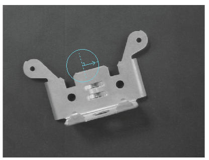
Be aware this is not the search region for locating line segments, which you can configure on the Region tab.
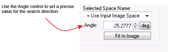
Click on the graphic to enable sizing and rotation handles and use it to specify the expected orientation of the line segments you want to locate. See the following examples for how to use the graphic:
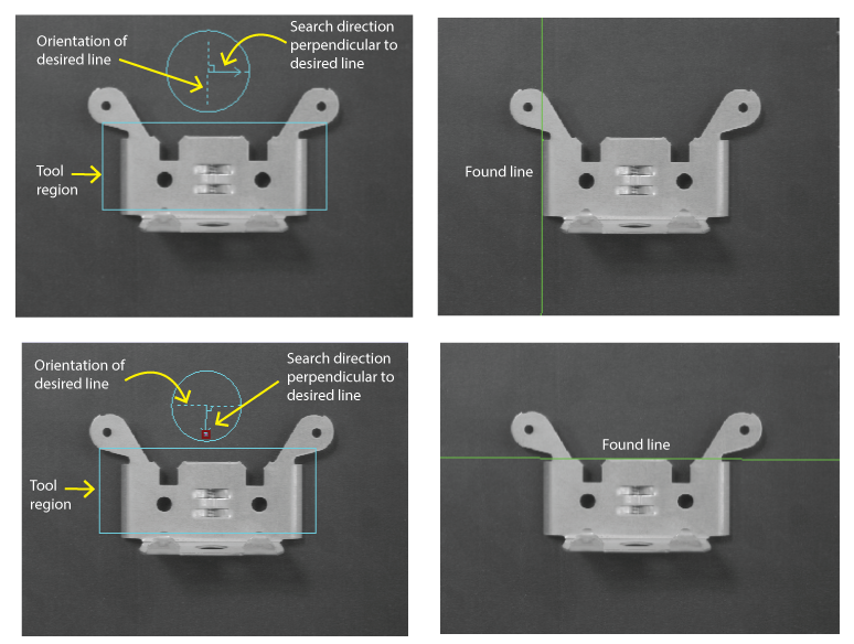
As you use the graphic be aware of the following:
The graphic does not designate a specific region to search for candidate edge points.
By default the tool searches a CogRectangleAffine for candidate edge points in the direction you specify. Use the Region tab to specify a limited region to search for edge points as your vision application requires. Use a Fixture tool to compensate for how the search region must be reoriented in successive runtime images.
The graphic does not specify the polarity of the edge points to search for.
If you specify a polarity that is not available along the search direction, the tool will not find candidate edge points.
The following parameters determine how a CogLineMaxTool detects edge points in the input image:
| Parameter | Description |
The tool uses this value to analyze the runtime image and generate a set of gradient vectors representing edge information. Use a small value when the features of interest in your images display sharp edges, where the transition between light and dark pixels occurs over a short distance. Increase this value for smoother edges in your images. | |
This value determines the number of areas used for gradient field projection. A small value allows the tool to analyze the image with finer granularity than a larger value, but might require more time for the tool to execute. A larger value can improve the execution speed of the tool but might not detect the edges you want the tool to locate. In general, use a value at least as large as your setting for Gradient Kernel Size in Pixels, but it can be set higher if the tool continues to locate the desired edge points. | |
Specify the minimum contrast for an edge to be considered a candidate edge for the feature you want to locate. Increase this value to locate edges of stark contrast and ignore edges where the transition between light and dark pixels is not as prominent, or lower this value when the contrast in the edges you want to locate in your images is small. The contrast of an edge is the absolute difference in average pixel values across the edge, in the range 0 through 255. Only edges with contrast greater than the value you specify are considered by the tool. For example, setting this value to 10 rejects edge points with a contrast below 10 pixel values. | |
| Normalized Contrast Threshold | Raise the value of this parameter to discard false edge points in bright areas of your image. Be aware that setting it to 1 discards all edge points, making the tool effectively nonfunctional. |
Use the Line Fitting tab to configure how the tool locates lines from candidate edge points:
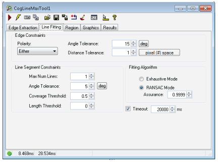
The tab has the following components:
Use the following parameters:
| Parameter | Description |
| Polarity | The polarity of the edge points to include in the line. |
| Angle Tolerance | The maximum allowable angle difference between an edge point gradient direction and then normal to the fit line. Increasing this value allows the tool to consider more edge points as inliers, changing the location of the found line segment. |
| Distance Tolerance | The maximum allowable distance between an inlier and a fitted line. As you increase the edge distance tolerance, you allow the tool to consider more edge points as inliers and change the location of the found line. |
Configure the following limitations:
| Parameter | Description |
The maximum number of lines you want the tool to locate. Be aware the edit control supports this parameter only when your VisionPro installation includes the VisionPro.LineMaxMulti license. See the topic Using VisionPro Security Keys for details on VisionPro security. Set this value to 0 to prevent the tool from returning any line results but still generate a set of outliers for use in your vision application. | |
The amount of rotation a found line segment can differ from the expected angle that you specify. A low value forces the tool to locate line segments that are more parallel with the gradient search direction. | |
The minimum acceptable ratio of inliers to the maximum possible number of inliers, or the minimum proportion of edge features along the line segment. For example, specifying a value of 0.5 allows the tool to locate a line segment even though edge points were not detected over 50% of the line. Use Coverage Threshold and Length Threshold simultaneously to meet your line fitting requirements. Be aware that specifying a value of 1.0 forces the tool to locate a line segment only when there are no gaps where no inliers were found. | |
| Length Threshold | Set the minimum acceptable length of a found line segment. |
Choose either of the following algorithms for fitting edge points to lines:
| Parameter | Description |
| Exhaustive Mode | All edge point combinations are evaluated for line fitting. |
The Random Sample Consensus method (RANSAC): An algorithm for robust fitting of edge points in the presence of many edge point candidates. The value for Assurance affects the likelihood that the best edge points will be selected for line fitting. |
Choose a Timeout value to specify the maximum execution time (msec) allowed to locate the number of requested line segments. If the tool has not finished by the end of the timeout period, it will stop and throw an exception.
Use the Region tab to define the the area of the input image where the tool searches for edge points.
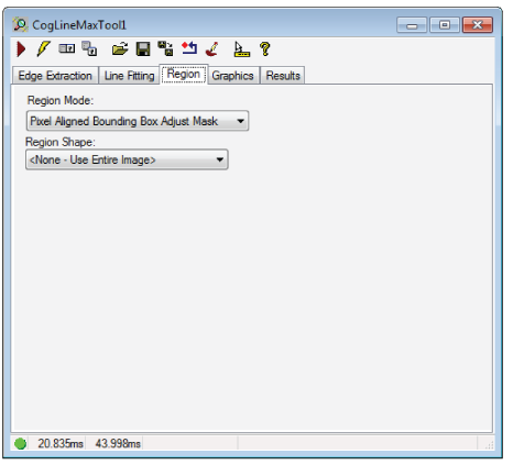
| Parameter | Description |
Defines the bounding box for the region.
| |
| Region | The shape of the search region. By default the tool uses a CogRectangleAffine. Selecting "None=Use entire image" means that the entire Current.InputImage becomes the search region. The set of region-defining parameters depends on the selected Region Shape. |
| SelectedSpaceName | The coordinate space in which the search region is interpreted. For more information, see Coordinate Space Names. |
| FitToImage | Centers the search region within Current.InputImage. |
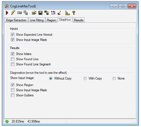
Use the Graphics tab to control which graphics the tool displays.
| Parameter | Description |
| Inputs |
|
| Results |
|
Diagnostics | Show Input Image: Determine whether or not the input image is recorded as part of the diagnostic record, and whether the image is copied to the record or saved in the record as a reference.
|
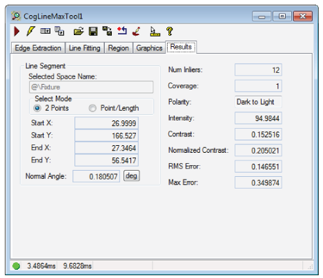
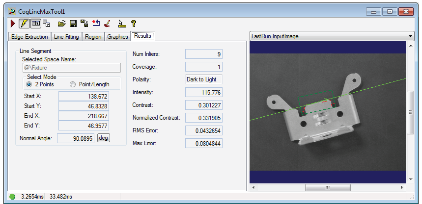
The tool returns the following information about found line segments:
- The (x,y) location, in coordinates of the selected space, for the start and end of the fitted line segment, including its NormalAngle
- The number of inliers (Inliers) and the proportion of inliers (Coverage) contributing to this line segment
- Its polarity (Polarity), intensity (Intensity) and amount of contrast (Contrast)
- A residual RMS fit error (RMSError), relative to the selected space of the input image, from the contributing inliers
- A MaxError reporting the distance of the farthest inlier from the line.
If you set the Max Num Lines parameter to 0, the tool returns no line segments but still generates information about edge results with outliers for use in your vision application through the CogLineMaxTool API.