Guided Pick or Place Application
This guide demonstrates how to implement a VGR Vision-Guided Robotics is an In-Sight Spreadsheet feature that uses machine vision to guide robot motion through Robotics String Functions and VGR commands. pick or place application. In this workflow, the vision system detects the part position and orientation, and returns alignment data that the robot uses to perform a corrected pick or place operation.
|
|
|
| Robot-mounted vision system | Stationary vision system |
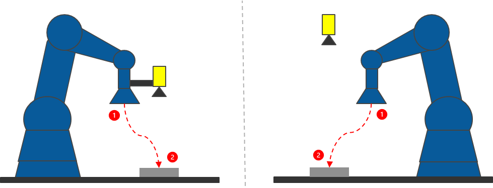
The overall workflow is identical whether the robot is picking or placing a part. In both cases, the vision system:
-
acquires an image of the part,
-
detects the part or placement target using a configured Feature Finder tool,
-
computes alignment offsets relative to a trained pose,
-
and returns position and rotation data to the robot controller.
The robot then applies the returned offsets to move to the corrected target pose and execute the operation.
In this example, the vision system locates a single part or placement feature. All other robot positions required by the application are assumed to be predefined and managed by the robot controller.
This approach is commonly used in applications such as:
-
Random picking, where the vision system corrects for part position and orientation before grasping and places the part at a known, consistent location.
-
Conveyor picking, where vision system compensates for part shift or rotation before picking and places the part at a known, consistent location.
-
Precision placement, where alignment offsets ensure accurate insertion into a fixture A fixture is a coordinate location on the image that keeps the tool in the place determined by the fixture. or assembly location.
Workflow Overview
A guided pick or place application follows this sequence:
-
Set up the device and system.
-
Perform hand-eye calibration.
-
Train robot poses.
-
Execute runtime alignment.
Device and System Setup
Before configuring the VGR job, ensure that the vision system and robot controller are properly installed and connected.
Perform the following steps to set up your system:
-
Mount the vision system.
-
Verify network communication.
-
Confirm that the vision system is discovered in In-Sight Spreadsheet.
-
Establish robot communication.
For more information, see Device and System Setup.
Building a Spreadsheet Job
Create a Spreadsheet job to define image acquisition Acquisition is the process or result of the vision system acquiring a new image., VGR functions, and alignment logic.
Make sure that your Spreadsheet job contains the following:
-
Image acquisition logic.
-
Feature finding tools for finding and aligning to parts.
-
Required Robotics String Functions (for example, VGRProcessCommand, VGRDefinePart, and VGRHandEyeCalibration).
For more information, see Building a VGR Job.
Calibration
Calibration establishes the spatial relationships required for accurate vision-guided operation. Depending on the application, this may include image calibration for the vision system as well as hand-eye calibration between the vision system and the robot controller.
Image Calibration
Image calibration establishes pixel-to-world scaling and measurement accuracy within the image. Image calibration is required in the following cases:
-
Images exhibit noticeable lens distortion
-
Precise dimensional accuracy is needed
-
The application requires improved positional accuracy
For more information about image calibration, see Image Calibration for VGR.
Hand-Eye Calibration
Hand-eye calibration defines the relationship between the robot coordinate system and the vision system coordinate system. This step is required for Vision-Guided Robotics applications to ensure that alignment results are correctly translated into robot motion.
Hand-Eye Calibration can be performed using either:
| Vision-Guided (Auto) Hand-Eye Calibration | The vision system automatically estimates calibration poses based on field-of-view coverage. The robot is guided to positions that span the calibration area, reducing manual pose planning. |
| Motion-Guided (Manual) Hand-Eye Calibration | The robot controller explicitly moves the robot through each calibration pose and triggers image acquisition at each position. This method provides full control over pose selection and sequencing from the robot program. |
For more information, see Hand-Eye Calibration.
Robot Pose Training
Before run-time execution, you have to train the robot with reference poses that define the nominal pick or place position. Training establishes the relationship between a known robot pose and the corresponding vision result for the part or placement location. This ensures that runtime alignment offsets are applied correctly.
For detailed instructions on training robot poses, see Train Robot Poses for Aligment.
Run-Time Alignment
Once calibration and training are complete, run-time alignment can be executed during production.
The program sequence during run time is as follows:
-
The robot moves to the image acquisition pose for the pick or place location and acquires an image.
-
The robot controller sends the Execute Pick or Place Alignment (XT) or Execute Pick or Place Aligment with Score (XTS) command using the PartID associated with the pick or place feature (for example, PartID = 1). For example:
XT,1,<Result Mode>,<current robot pose>
-
The vision system returns the alignment results:
XT,<Result Status>,<run-time pick pose>
-
The robot then applies the received position and rotation data to execute the corrected pick or place operation.
This completes the Vision-Guided Pick or Place workflow using a single trained reference pose. You can expand the same approach to support multiple parts or more complex applications.