Vision-Guided (Auto) Hand-Eye Calibration
This guide provides a step-by-step walkthrough for Vision-Guided (Auto) Hand-Eye Calibration in a VGR Vision-Guided Robotics is an In-Sight Spreadsheet feature that uses machine vision to guide robot motion through Robotics String Functions and VGR commands. application. For more information, see Hand-Eye Calibration.
Prerequisites
Before starting Vision-Guided (Auto) Hand-Eye Calibration, ensure the following:
-
The vision system is properly mounted, connected, and discovered in In-Sight Spreadsheet.
-
A Spreadsheet VGR job A job is a user-configured program in In-Sight Spreadsheet consisting of functions and designed for specific applications. You can create and edit jobs using the In-Sight Spreadsheet interface, and load them on a vision system for deployment in a live environment. has been created and configured, containing:
-
Image acquisition Acquisition is the process or result of the vision system acquiring a new image. logic
-
The required Robotics String Functions used for Hand-Eye Calibration (VGRProcessCommand, VGRDefinePart, and VGRHandEyeCalibration)
-
A Feature Finder tool is configured and reliably detectable, as it serves as the calibration target.
-
-
Robot communication is established and verified.
For more information about building a Spreadsheet job for VGR applications, see Building a VGR Job.
Setup
Once you have created a job with the required Robotics String Functions, open the VGRHandEyeCalibration property sheet.
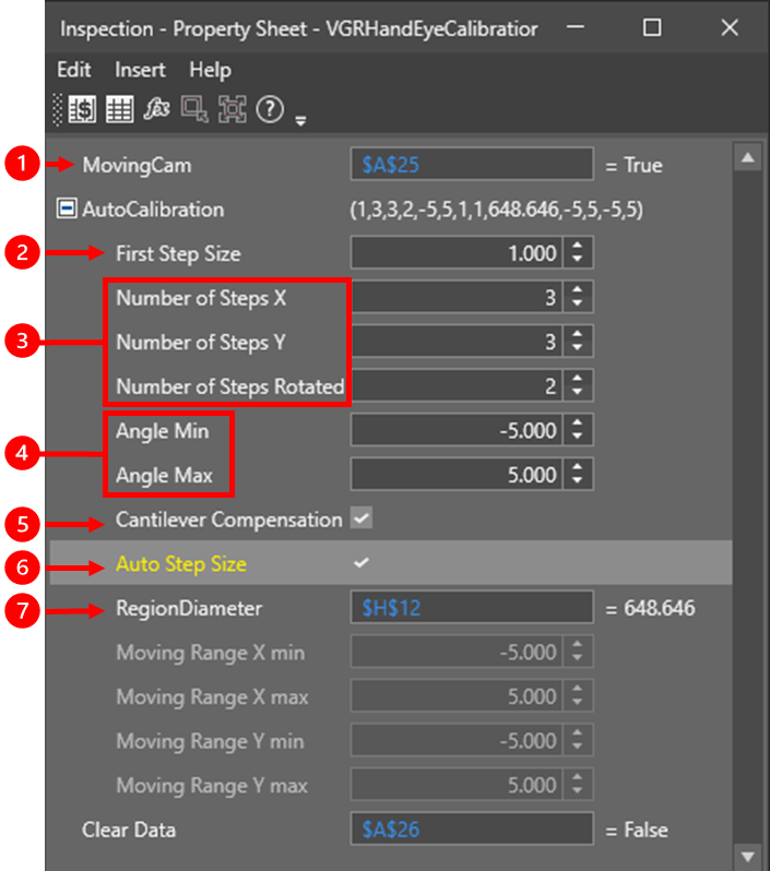
Auto-calibration behavior is controlled through the VGRHandEyeCalibration tool settings. These parameters determine how the vision system calculates robot motion during calibration. These values vary depending on the application.
|
|
1 |
Moving Cam Specifies the vision system mounting configuration:
|
| 2 |
First Step Size Specifies the initial small motion used to estimate the usable FOV before larger calibration moves are generated. |
|
| 3 |
Number of Steps (X, Y, Rotation) Controls how many calibration poses are collected in each direction. Increasing the number of steps generally improves calibration accuracy, but increases calibration time. |
|
| 4 |
Angle Min / Max Limits the rotation range used during calibration based on the mechanical constraints of the robot. |
|
| 5 |
Cantilever Compensation When enabled, the vision system adjusts X and Y motion during rotation to keep the calibration target near the center of the FOV. When disabled, you must manually specify the rotation range limits for the pattern to stay in the FOV. |
|
| 6 |
Auto Step Size (default: enabled) When enabled, the vision system automatically calculates the X and Y motion range needed to cover the full FOV while keeping the calibration target within view. When disabled, you must manually specify the motion ranges, and the vision system computes pose steps within those limits. |
|
| 7 |
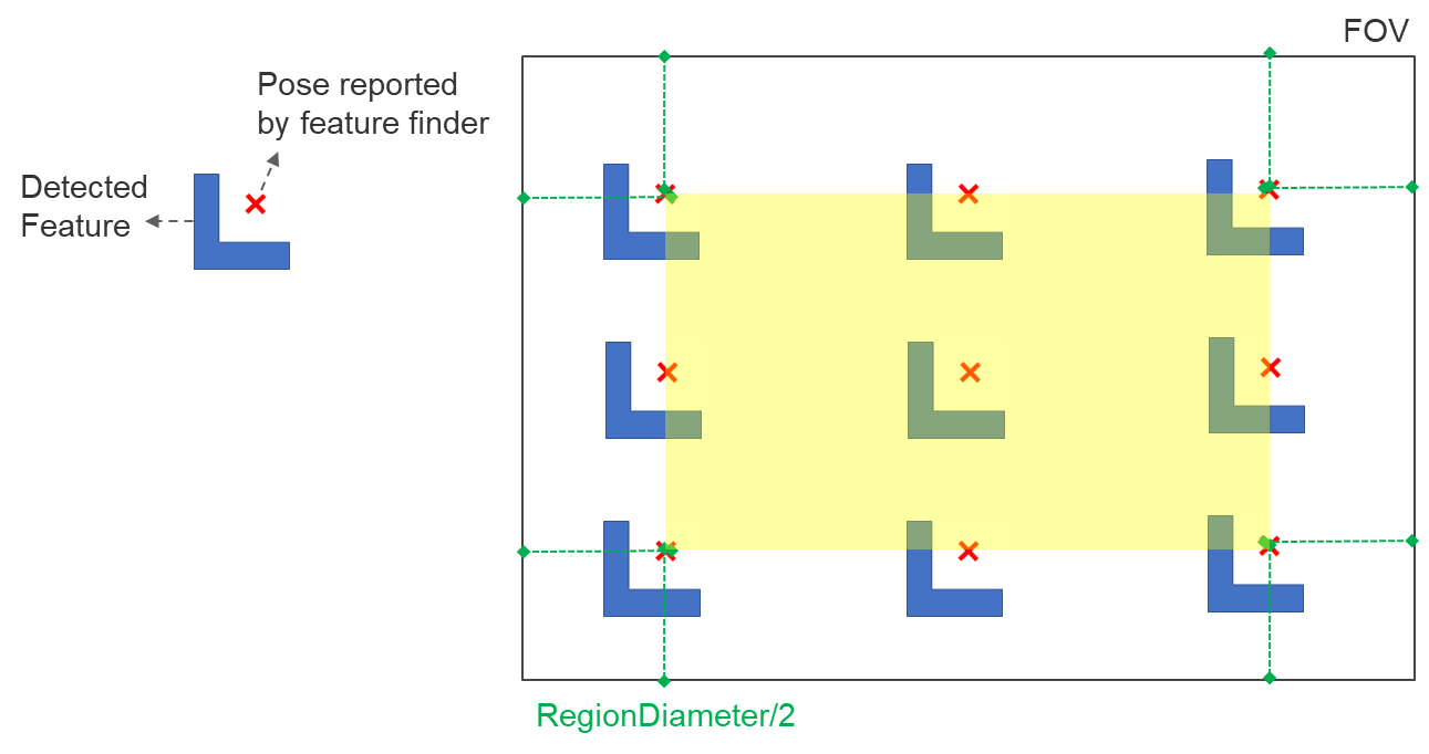
RegionDiameter Defines the size of the region around the detected feature that must remain within the area of the FOV highlighted in yellow in the following image:
Use this parameter to prevent the calibration target from moving out of view when Auto Step Size is enabled. |
Once the auto-calibration settings in VGRHandEyeCalibration are configured, switch to the robot controller. From the robot controller, send the required VGR commands to the vision system to initiate Hand-Eye Calibration.
Program Sequence
The program sequence for auto-calibration is as follows:
-
Move the robot arm to the starting pose.
-
Place the part in the center of the vision system FOV.
-
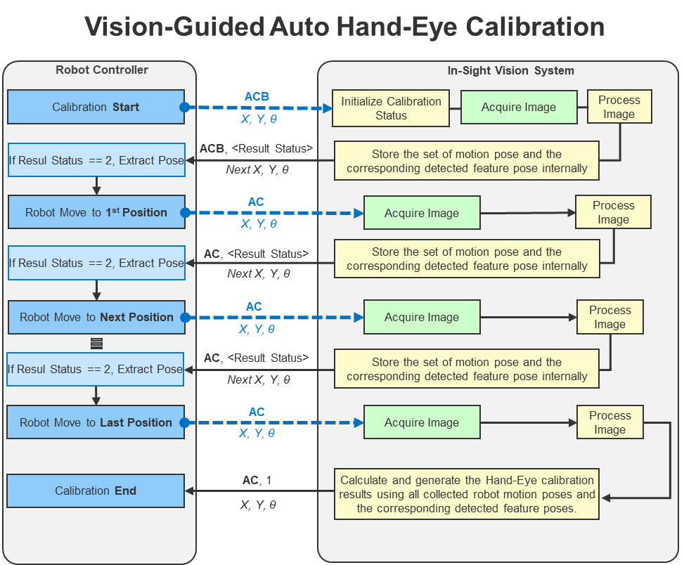
The robot controller sends an Auto-Calibration Begin (ACB) command to the vision system with the current robot pose and rotation coordinates.
-
The vision system computes the next target pose using the configured auto-calibration settings, and returns an ACB response to the robot controller with position and rotation data for the next pose.
-
If the status field on the received response has a value of 2, the system continues the sequence. If the status field has a value of 1, the sequence ends. If the status field is less than 0, the system raises an error and ends the sequence.
-
If the sequence continues, the robot controller extracts the position and rotation data of the next robot pose from the ACB response.
-
The robot controller moves the robot to the pose corresponding to the extracted position and rotation data.
-
The robot controller sends an Auto-Calibration Execute Step (AC) command to the vision system, including the current robot pose.
-
The vision system acquires and processes an image, locates the calibration features, calculates the next target pose, and returns an AC response to the robot controller with position and rotation data for the next pose.
-
The command-resonse cycle repeats until the system goes through all calibration poses.
-
After the last calibration pose is complete, the vision system returns an AC response with a status field value of 1, indicating that the calibration sequence has ended successfully and saved to the job.
The following diagram illustrates the workflow for vision-guided auto-calibration, showing the command-response interaction between the robot controller and the vision system: