This topic contains the following sections.
- Develop the Conceptual Approach to Solving the Application
- Implement the Conceptual Approach
- Step 1: Fixture the Part
- Step 2: Locate the Center of the Dial
- Step 3: Create a Baseline Through the Dial Center
- Step 4: Find a Point on the Needle Centerline
- Step 5: Establish a Line from Dial Center through the Needle
- Step 6: Measure the Angle from the Baseline to the Needle
- Using a Dimensioning Application
This topic provides an overview of how to use the dimensioning tools to solve dimensioning applications.
Before beginning to develop your application, analyze the problem you are trying to solve and develop a conceptual approach to solving the problem. Once you understand the high-level steps to solving the application, select, configure, and apply the appropriate dimensioning tools.
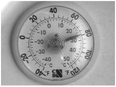
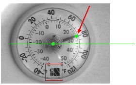
In this example, the application is to verify that the indicator needle on a dial thermometer is pointed in the correct direction. (This application might be used to verify the accuracy of the thermometers by placing them in a chamber of known temperature, then verifying that their readings are correct.) The following figure shows an image of the part:
The following list gives one conceptual approach to solving the problem of verifying that the needle is pointing in the correct direction.
-
Fixture the part. Since the thermometers may appear at any angle or offset within the image, start by
identifying a distinctive pattern on the part and using that to create a fixture. Once the fixture is established,
subsequent vision tools will operate in that fixtured space.
-
Locate the center of the dial.
-
Establish a baseline. Defining a baseline that passes through the center of the dial will provide a reference
line from which to measure the angle of the needle.
-
Locate a point on the center line of the needle.
-
Establish a line that passes through the center point and the point on the needle. The angle between this
line and the baseline gives the needle angle.
-
Measure the angle between the two lines.
Once you have established the approach you will use, apply VisionPro vision tools and dimensioning tools to implement the application. The following sections show how the application described above could be implemented in VisionPro. This example uses QuickBuild.
Note: There are many conceptual approaches and implementations that can be used to solve dimensioning applications. The approach shown here may not be appropriate for all applications.
In this application, the CogPMAlignTool is used to locate each part for fixturing. You create, configure, and link a CogPMAlignTool by following these steps:
-
Add a CogPMAlignTool to the toolgroup and link the Job's Image Source's output image
to the CogPMAlignTool's input image:
-
Grab a training image and train the logo as a pattern:
Note: Aligning the pattern origin with an easily recognizable feature in the image can make it easier to detect problems with the pattern location step.
-
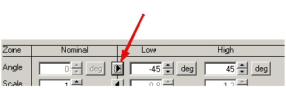
Since the thermometers may be rotated, enable rotation in the CogPMAlignTool's Run Params
tab (in this case,
the default range of -45° to +45° is sufficient to handle the expected rotation):
-
Create a
CogFixtureTool
and link the CogPMAlignTool's output pose to the CogFixtureTool's
input transformation
(make sure to link your image source's output image to the CogFixtureTool's input image):
Note: The approach shown, of linking the CogPMAlignTool's output pose directly to the CogFixtureTool's input transformation will work correctly as long as you do not enable independent X- and Y- scale degrees of freedom in the CogPMAlignTool. Note that you can also link the individual translation and rotation properties instead of the pose.
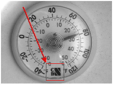
Running the toolgroup should cause the CogPMAlignTool to display its result graphics on the found logo:
The molded features and many reflections near the center of the thermometer dial make it difficult to use a pattern location tool to find the center of the dial directly. Because the thermometer dial has several strong circular features, the CogFindCircleTool is an appropriate choice for locating the center of the dial indirectly.
-
Add a
CogFindCircleTool
to the toolgroup and link the CogFixtureTool's output image to the CogFindCircleTool's
input image (keep in mind that the CogFixtureTool sets the selected space of its output
image to be the fixtured space; all
the subsequent tools should to run in this fixtured space):
Note: At this point you can also create a link from the CogFixtureTool's output image to the tool group's outputs collection. You can do this by simply dragging a link from the CogFixtureTool's OutputImage terminal to the ToolGroup Outputs collection. Creating this link will cause the tool group edit control's display to show the result graphics from all of the tools that use the fixtured image as input.
-
Now configure the CogFindCircleTool by placing the expected arc graphic on one of the circular features in the
image. You should position the arc and the caliper regions so that a high-contrast circular feature is near the
center of each caliper region and so that there are a minimal number of extraneous features within the caliper
regions, and you should adjust the number of calipers to provide good coverage across the expected arc:
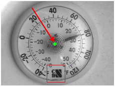
Running the toolgroup should now display both the found pattern and the found circle:
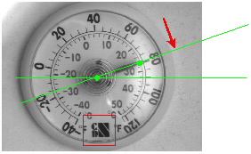
In this application, the angle of the needle is measured relative to the dial face. This step shows how to create a horizontal baseline that passes through the dial center.
-
Create a
CogCreateLineTool
and link the CogFixtureTool's output image along with the CogFindCircleTool x and y center points:
Note: Not linking to the CogCreateLineTool's InputLine.Rotation property means the tool will use its default value of 0° for the rotation. You can specify a different value for this property using the tool's edit control.
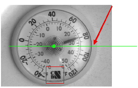
Running the toolgroup should now display the baseline (in addition to the other tool results):
The simplest method of locating the center of the indicator needle is to use a CogCaliperTool.
Note: The methods described in this step assume that the needle angle will only vary by a few degrees. The application assumes that if the needle lies outside of the caliper input region, the part is automatically bad.
-
Create a CogCaliperTool and link the CogFixtureTool's output image to the CogCaliperTool's
input image:
-
Now configure the CogCaliperTool's input region so that it lies across the needle. Keep in mind
that since you have linked the CogFixtureTool's output image to the CogCaliperTool's input image
the input region will move with the part:
-
Now configure the CogCaliperTool to expect an edge pair of appropriate polarity and size:
Running the toolgroup should now display the edge pairs (in addition to the other tool results):

Given two points (the dial center and the needle point located in the previous step), you can easily create a line along the needle.
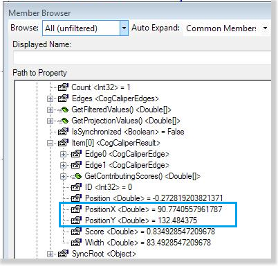
Right-click on the CogCaliperTool and choose Add Terminals. Select the (X,Y) coordinates of the result and click Add Output.
-
Create a
CogCreateSegmentTool
and link the CogFixtureTool's output image along with the links as shown:
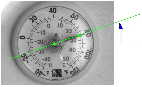
Running the toolgroup should now display the new segment (in addition to the other tool results):

Now that you have established the two lines, you can measure the angle between them.
Note: The CogAngleLineLineTool measures the angle between lines, not segments or segments and line. To use the line segment created in the previous step, you must link its GetOutputSegment.CreateLine property.
-
First create a
CogAngleLineLineTool
and link the CogFixtureTool's output image along with the
baseline from the CogCreateLineTool (step 3) and the line output of the CogCreateSegmentTool :
Running the toolgroup should now display the new line (in addition to the other tool results):
To view the measured angle, simply open the CogAngleLineLineTool and click on its Results tab:
Once you have created a dimensioning application using QuickBuild, you can save the application as a .VPP file develop it further with the VisionPro Application Wizard. You can also reimplement your application using the native CogMath interface.