This topic contains the following sections.
The Fixture edit control provides a graphical user interface (GUI) for the simple CogFixtureTool vision tool and its components.
The Fixture tool attaches a fixtured coordinate space to an input image and provides an updated image as output for use by other tools. You must supply a nonqualified coordinate space name for the fixtured space and a CogTransform2D that defines the fixtured coordinate space relative to the unfixtured space.
The Fixture tool acquires the necessary information to perform the fixturing operation from the input image and run-time parameters you supply. The unfixtured space name is the selected space name in the input image. You obtain the 2D transformation from another vision tool, such as CogPMAlignTool. The edit control allows you to edit the various components of this transform before attaching it to the coordinate space tree of the specified image.
A Fixture edit control exposes the following default tool input and outputs for creating data links:
- InputImage
- UnfixturedFromFixturedTransform
- TranslationX
- TranslationY
- Rotation
- OutputImage
Note that although the Fixture edit control exposes the UnfixturedFromFixtured 2D transformation as a default input, if you want to adjust the translation and rotation components of the fixturing transformation, you should use the specific inputs for translation and rotation. Using the UnfixturedFromFixturedTransform input from another vision tool may introduce unexpected discrepancies in your fixturing. For example, the CogPMAlignTool tool may add a small scaling factor to its result transformation, which can cause problems if you have obtained a scaling measurement by previously calibrating your input image. You almost never need to adjust any other components of the transformation other than translation and rotation. Whichever way you choose to receive transformation data, either from the UnfixturedFromFixturedTransform input or from the individual inputs for the translation and rotation components, you must not connect both types of transformation input at the same time.
The Fixture edit control includes the following components:
- A row of control buttons at the top left.
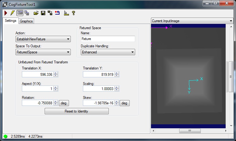
- A tool display window that displays the Fixture tool image buffers, which include Current.InputImage and LastRun.OutputImage. These buffers contain the input image to which the tool attaches the fixtured coordinate space and the output image from the tool's last run. Right click the tool display to bring up menu options that include zooming in or out of the image or showing a pixel or subpixel grid.
- A set of tabs organized by function. These functions include parameter settings to run the tool and settings to display tool graphics, such as fixtured and unfixtured axes. Pressing the Control + Tab keys scrolls through the set of tabs.
- A status bar at the bottom left of the control. A green circle indicates that the tool ran successfully; red means the tool ran unsuccessfully. The status bar also displays the time to run the tool and any error codes or messages. The first time that the status bar displays is the raw tool execution time. The second includes the time needed to update the edit control. Controls only update when they are visible.
The Fixture edit control has several buttons that are common to most VisionPro controls.

This table describes the buttons at the top left of the edit control.
| Button | Description |
 | Runs the Fixture tool. You must have an image available in the Current.InputImage buffer (equivalent to the InputImage). This button invokes the Run method. |
 | Toggles electric mode. When selected, the Fixture tool runs automatically if certain parameters have changed. When the edit control is in electric mode, these parameters are indicated by electric bolt icons. |
 | Opens or closes the local tool display window. This window has a selection box that you use to specify the image buffer you want to view. |
 | Opens one or more floating tool display windows, providing an additional tool display window. As with the local tool display window, you can specify the Caliper image buffer to view. |
 | Loads a VisionPro persistence (.vpp) file, which contains a set of saved properties for this vision tool object type. Loading a persistence file for another object type throws an error and the load is unsuccessful. For more information about VisionPro persistence features, see the topic Persistence in VisionPro. |
 | Saves the current properties of the underlying tool to a VisionPro persistence file. You have the option to save either the entire tool or the tool without its images or results. |
 | Saves the current properties of the underlying tool to a new VisionPro persistence file. |
 | Resets the underlying tool to a default state. |
 | Enables or disables the display of tooltips for individual items in this edit control. |
 | Opens this help topic. |
The Fixture edit control has two image buffers. The Current.InputImage buffer uses the image supplied by the underlying Fixture tool's InputImage property. The LastRun.OutputImage buffer holds the output image that results from the fixturing operation. The output image is a new COM object that references the same pixels and space tree, as the input image. Because of this, the newly attached fixture space is accessible from either image. The space was attached to the shared tree, not just to the tree associated with the output image. The selected space names, however, are not shared. Each image has its own selected space name.
Use the Settings tab to control the run-time parameters for the Fixture tool.
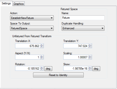
These parameters include the name of the fixtured space, the selected space name of the output image, and the transformation that maps points from the fixtured space to the unfixtured space. When the edit control is in electric mode, electric bolt icons indicate parameters whose changes cause the tool to run automatically.
| Feature | Description |
Action | Determines how the Fixture tool should process the input image. |
| FixturedSpaceName | Name of the fixtured coordinate space to attach to the CogCoordinateSpaceTree of the input image. This must be a valid nonqualified space name. Equivalent to the FixturedSpaceName property. |
| Duplicate Handling | Specifies how fixtured space name collisions are handled. Select FixturedSpaceNameDuplicateHandling to generate a warning when one tool overwrites the space created by another tool, FixturedSpaceNameDuplicateHandling to silently ignore collisions. |
| Space to Output | Specifies whether the selected space name of the output image will be a copy of the fixtured space name or a copy of the unfixtured space name. The output selected space name is always a fully-qualified space name. Equivalent to the SpaceToOutput property. |
Unfixtured from Fixtured Transform | Changes the values of the components of the UnfixturedFromFixturedTransform that will be attached to the input image's coordinate space tree. In a typical vision application, you calibrate an image before using it as input to the Fixture tool and have therefore obtained a desired scaling measurement from the calibration. You should not need to adjust the Scaling component of the UnfixturedFromFixtured transform. Doing so may affect the accuracy and validity of the resulting fixtured space. Note that you can specify the rotation and skew components in either degrees or radians, although the underlying tool maintains these values in radians. |
| Reset to Identity | Creates a new linear identity transform and sets it as the tool's UnfixturedFromFixtured transform. |
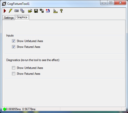
Use the Graphics tab to control what is displayed in the local and floating tool displays.
When the control is in electric mode, electric bolt icons display parameters that cause the tool to run automatically if parameter values change.
| Feature | Description |
Inputs | You can display the following results graphics:
|
Diagnostics | You can display the following results graphics:
|