This topic contains the following sections.
- What Does Linescan Camera Calibration Do?
- Coordinate Spaces in Linescan Camera Calibration
- Linescan Acquisition Distortion Correction
- Camera Rotation
- Camera Tilt
- Radial Distortion
- Non-linear Translation Distortion
- 2D Warping
- Using Linescan Camera Calibration
- Calibration Phase
- Run-Time Phase
- Calibrated Space Origin
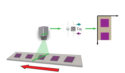
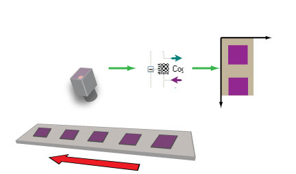
The CogCalibCheckerboardTool allows you to perform nonlinear calibration upon linescan cameras. This topic describes the support provided by the tool for linescan cameras and explains how to use it.
Note: Before reading this topic, make sure that you understand the basic principles of Calibration and Fixturing and of nonlinear calibration using the CogCalibCheckerboardTool.
Linescan camera calibration, like area-scan camera calibration, is performed by acquiring an image of a calibration plate, then calling a camera calibration function to perform the calibration.
Note: Linescan camera calibration requires the use of a checkerboad calibration plate that meets the requirements specified in the topic Checkerboard Calibration Plates.
Linescan camera calibration performs two functions:
- It establishes a calibration transformation that maps points from a physical space defined by the planar motion associated with the linescan camera to the image space of the image acquired by the camera.
- It creates an unwarped version of the image acquired by the camera. The unwarped image removes the distortion associated with camera rotation, camera tilt, optical distortion, and uneven pixel size or spacing.
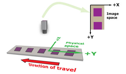
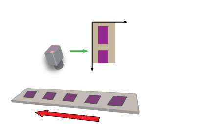
The physical coordinate system for linescan camera calibration is established as follows:
- The Y-axis of physical space is defined by the apparent movement of the linescan camera. The positive Y-direction is defined by scan order (the Y-value increases in the order in which lines are acquired).
- The X-axis of physical space is normal to the Y-axis. The positive X-direction defines a left-handed coordinate system.
- The origin point (0,0) of the space is user-defined. In the case where the linear motion is finite, the origin may be at the center of the motion or at either end. In the case where the linear motion is infinite, as with a web, only the X-coordinate is meaningful.
- The X- and Y- units are defined by the grid pitch that you specify during calibration.
The image coordinate system is the same as for other VisionPro images.
The following figure illustrates the coordinate spaces associated with linescan camera calibration.
Different types of distortion can be present in images from a linescan camera.
If the linescan camera is rotated with respect to the direction of linear motion (the image sensor is not perpendicular to the direction of travel), features in acquired images will be skewed, as shown in this figure:
As long as the camera rotation is within +/- 5°, linescan camera calibration can rectify the distortion.
If the linescan camera is tilted with respect to the plane of motion (the image sensor is not parallel to the plane of motion), features in acquired images will be exhibit a change in their apparent aspect ratio, as shown in this figure:
As long as the camera tilt is within +/- 5°, linescan camera calibration can rectify the distortion.
Images acquired with a linescan camera are subject to the same types of radial distortion as images acquired with area-scan cameras. The optical distortion in a linescan image is limited to the X-direction, so rather than the classic "barrel distortion" or "pincushion distortion", the distortion manifests itself as nonlinear distortion across the X-dimension of the image, as shown in this figure:
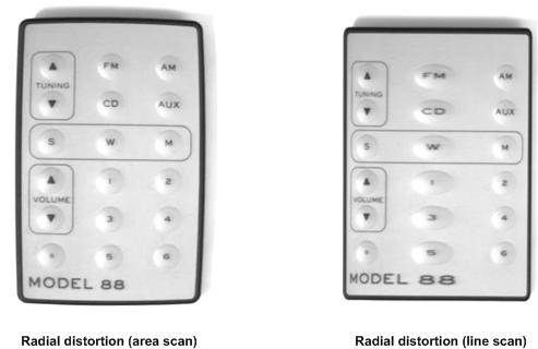
Linescan camera calibration uses the same techniques as the standard nonlinear calibration tool to remove this distortion.
To the extent that the linear motion is not precisely synchronized with the encoder pulses that drive the acquisition of individual lines, linescan images may exhibit nonlinear distortion in the Y-direction. This distortion is not corrected by the linescan camera calibration tool.
The types of distortion previously described, such as camera tilt and camera rotation, can be corrected with linescan calibration and its one-dimensional warping transformations.
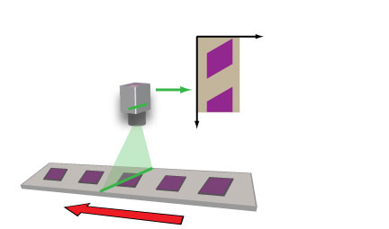
For some production environments, the 1D transformations might not be sufficient. For example, if the object under inspection can be tilted with respect to the direction of linear motion, features in acquired images will demonstrate some degree of perspective distortion, as shown:
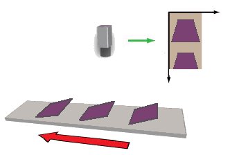
For these cases, linescan calibration offers a 2D warping option.
Be aware that when you use the 1D warping transformation, the image of your calibration plate needs to capture the width of the plate while the height can be of arbitrary size. When you choose the 2D warping transformation, however, the calibration image must be the same width and height as your run-time images.
This section tells how to perform linescan camera calibration. As with all VisionPro calibration tools, the tool is used in two phases. First, an image of the calibration plate is acquired and the calibration is computed. This is called the Calibration Phase. Once the calibration is computed, the tool is run once for each acquired image. The calibration tool unwarps the input image and applies the calibrated space to the image's coordinate space tree. This is called the Run-time Phase.
To perform linescan camera calibration, follow these steps:
- Rigidly mount the camera so that its image sensor is perpendicular to the direction of travel and parallel to the plane of travel (within +/- 5°).
- Adjust the camera focus so that a sharp image at the plate surface can be acquired. Note: Moving the camera, changing its lens, focus, or aperture will invalidate the calibration once it has been computed. Make sure the camera is where you want it before proceeding.
- Affix the calibration plate so that its movement relative to the camera is the same as the parts that are being imaged. If your physical configuration has a meaningful origin and you are using a calibration plate with a fiducial mark, place the mark so that it indicates the desired physical position. The plate should be sufficiently large that the plate fills the width of the image. Note: The orientation of the plate is ignored by the tool. The plate itself does not need to be aligned to the direction of travel.
- Accurately measure and record the distance between the surface of the calibration plate and the camera's image sensor.
-
Acquire an image of the plate.
If you are using the 1D warping transformation option, the image should be large enough to contain at least ten rows of calibration plate squares but there is no upper limit on the size of the image and there is no requirement that the image be filled in the vertical dimension by the plate. If you are using the 2D warping transformation option, the calibration image must match the height and width of the desired run-time images.
The following figure shows examples of valid calibration images: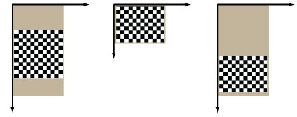
Note: The calibration image's coordinate space tree's pixel space to selected space transformation must not include any rotation. If the calibration image has been rotated, and that rotation is recorded in the image's coordinate space tree, the calibration function will throw an error.
- Compute the calibration specifying the correct Nonlinear Linescan option (1D or 2D). Although it is not a requirement, specifying the distance from the calibration plate to the image sensor (in the same units in which the grid pitch is specified) will improve the accuracy of the computed calibration.
- Specify whether or not the calibration plate includes a fiducial mark.
In addition to reporting whether the calibration was successful, the calibration tool also computes and reports the RMS error for the calibration. You can use this information to assess the accuracy of the calibration.
At run time, simply acquire an image using the same camera and configuration used for calibration, supply it as input to the tool, and run it. If you using the 2D warping option, the images must have the same width and height as your calibration image.
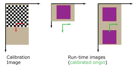
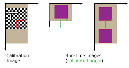
The linescan camera calibration tool computes the origin of the calibrated space in the output differently depending on whether the calibration plate image includes a fiducial.
-
If a fiducial is present on the calibration plate, the calibrated space origin location
in the output image is defined by the detected origin location in the calibration image's
image space. If the run-time image is shorter than the calibration image, this may place the
origin outside of the run-time image, as shown in the following figure:
-
If no fiducial is present on the calibration plate, the calibrated space origin location
in the output image is defined to be the offset of the center of the calibration image.
If the run-time image is shorter than the calibration image, this may place the
origin outside of the run-time image, as shown in the following figure: