Use a SurfaceFX tool in vision applications where you want to visualize surface effects such as bumps, dents, holes, scratches and other raised or sunken features on generally flat surfaces. A SurfaceFX tool accepts four images of the same stationary object under different lighting conditions and generates a CogImage8Grey image which highlights features that are raised above or below the average surface level.
The following figure shows a collection of input images and the output image a SurfaceFX tool will generate to highlight the defects they all contain:
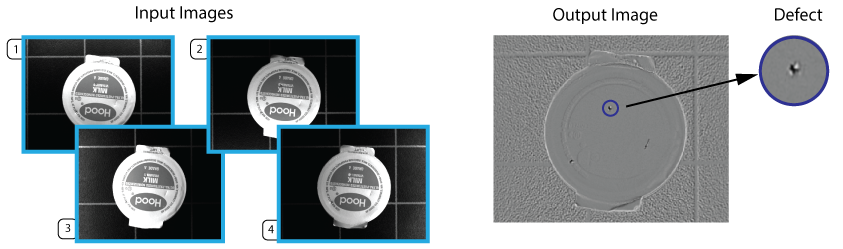
Other vision tools (Blob, LineMax, PatInspect) can analyze the output image from a SurfaceFX tool and evaluate the results based on the needs of your vision application.
See the following sections for more information:
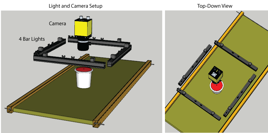
A SurfaceFX tool requires four input images of the same scene taken under different lighting conditions. A typical application uses four discrete lights at different orientations where the camera views the object through the center of the setup:
The illumination must be different for each input image by precisely controlling which of the four lights is active during acquisition. Specifically:
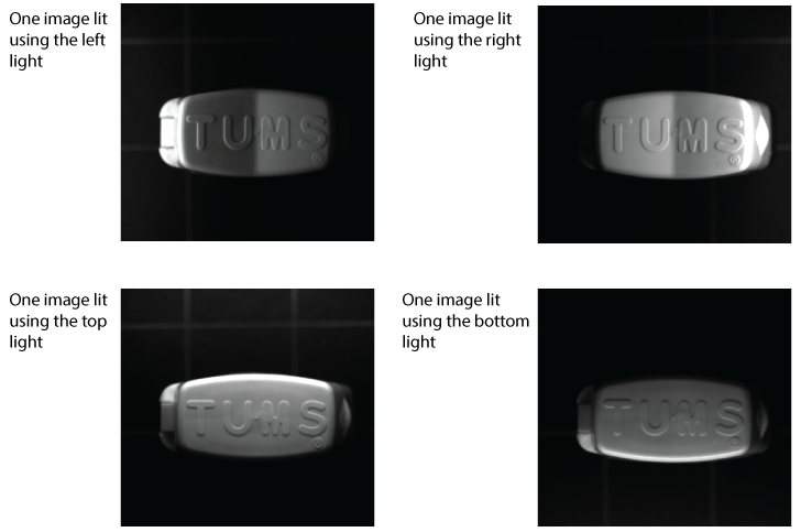
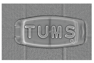
A SurfaceFX tool uses these images to estimate the three-dimensional shape of the physical scene. The output image shows the flat portions of the 3D surface as uniform grey and highlights the highly-curved sections of the surface as white if the surface curvature is concave-down or black if the surface curvature is concave-up:
A vision application that uses a SurfaceFX tool must support lights that can be turned on and off individually. Contact your Cognex sales representative for a recommendation.
In ideal vision applications using a SurfaceFX tool, the object does not move within the field of view of the camera as it acquires all the necessary input images. This generates the best results for an output image clearly showing the 3D features your application wants to examine. Cognex recommends the object being analyzed by a SurfaceFX tool come to a standstill for best results.
In many vision applications, however, an object will experience translation along a specific direction during the four image acquisitions. As the amount of motion increases, the quality of the output image will degrade. As you develop your vision application you must determine how to handle the perceived distance your object will travel.
To compensate for the perceived motion of your object as it passes within the field of view of the camera, you can choose to use a region of interest and a fixturing method in order to determine a new coordinate system to place your SurfaceFX tool so that the position of the region corresponds to the features of the object. For example, your application might use a PMAlign tool to locate a pattern on each input image and a Fixture tool to create the new coordinate space. A SurfaceFX tool can be placed relative to the new coordinate space and its region of interest will track the motion of the object.
Be aware any application that creates a new coordinate space to track the motion of the object must specify a region of interest for a SurfaceFX tool. VisionPro will report an error if you try to examine the entire image in the new coordinate space. In addition, the bounding box of the region must exist completely on the pixels of each input image. VisionPro will also report an error if the bounding box exists outside the edge of any input image.
Your VisionPro installation includes a QuickBuild Sample Job SurfaceFX_MovingPart to demonstrate a SurfaceFX tool in an application that compensates for object motion. See the section Sample Applications for details.
You can choose to disregard any perceived motion of your object as it passes within the field of view of the camera. This allows you to use the entire input image without specifying a region of interest. Be aware, however, that the quality of the output image will degrade in proportion to the amount of motion. You might have to experiment to determine if the amount of degradation is acceptable for your application.
Your VisionPro installation includes a QuickBuild Sample Job SurfaceFX_StationaryPart to demonstrate a SurfaceFX tool on a stationary part. See the section Sample Applications for details.
Depending on how you use a SurfaceFX tool in your vision application, be aware of the properties the tool supports for the input images you acquire. The SurfaceFX tool edit control and the CogSurfaceFXTool API support the following properties to store the four input images:
Using these properties you can acquire the images in any order suitable for your production environment. Be aware, however, that the CogSurfaceFXTool API also supports the InputVisionData property, which is a CogVisionDataContainer. VisionPro allows you to set the value of InputVisionData to a custom CogVisionDataContainer that you create and initialize. VisionPro assumes that the keys in the CogVisionDataContainer have been set as follows:
- The first key contains the image lit from the right.
- The second key contains the image lit from the bottom.
- The third key contains the image lit from the left.
- The fourth key contains the image lit from the top.
If the images in your CogVisionDataContainer appear in a different order, the SurfaceFX tool will generate unusable results.
See the documentation for the InputVisionData for details.
Be aware of the following limitations when using a SurfaceFX tool:
- Be aware a SurfaceFX tool cannot tolerate any change in rotation or scale between your input images. In such applications the tool will not report an error but return generally poor results in the form of an non-usable image.
- If your application does not compensate for any movement of the object between the first and last input image, your results can be unpredictable. Cognex recommends none or minimal movement of the object as your application executes, or that you compensate for movement by creating a new coordinate system based on found features of your object and locate a region of interest for your SurfaceFX tool relative to this new coordinate system.
- The tool does not produce a CogImage16Range output image, and you cannot view a 3D display of the surface.
In some applications, the four input images can support a variety of user-defined 2D coordinate spaces, or support different coordinate space transforms between the pixel space (#) and the root space (@). See the topic Coordinate Spaces for details on coordinate spaces in VisionPro.
The SpaceTreeMode property allows you to specify which coordinate space tree to copy to the output image, choose to merge the coordinate spaces from the all of the input images.
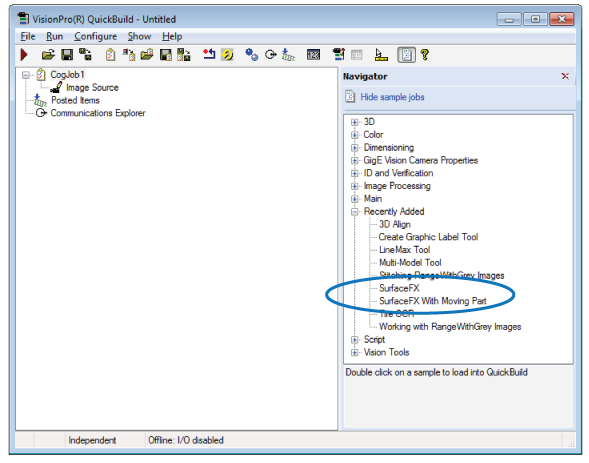
Your VisionPro installation includes two QuickBuild sample Jobs that demonstrate the use of a SurfaceFX tool:
- The Job SurfaceFX_StationaryPart demonstrates a SurfaceFX tool on four image files and uses a Blob tool to detect the defects the output image contains.
- The Job SurfaceFX_MovingPart also uses four image files, but is structured as if the parts translate from one image to the next. The Job uses PMAlign tools and Fixture tools to ensure the region of interest for a SurfaceFX tool compensates for the change in position of the object.
Find these sample Jobs in the QuickBuild Navigator pane:
Your VisionPro installation also includes a programmatic use of the CogSurfaceFXTool API. Locate the solution file SurfaceFXDemo.sln in the directory %VPRO_ROOT%\samples\Programming\VisionTools\SurfaceFXDemo\C#. The programming sample allows you to capture images from the image files stored in %VPRO_ROOT%\samples\Programming\VisionTools\SurfaceFXDemo\C#\Images or a live acquisition environment using a CC24 Cognex Communication Card, a CFG-8704e frame grabber, a light setup using four separate lights, a GigE Vision camera and a third-party strobe controller.
The following figure shows the sample application using static images:
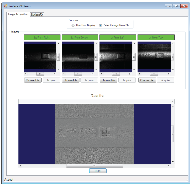
Read the comments within the source files for more information on how to use the sample application.