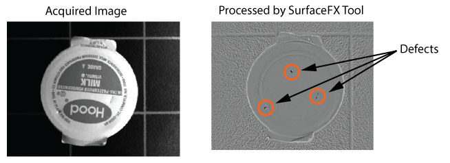
The SurfaceFX tool edit control provides a graphical user interface to the CogSurfaceFXTool, which accepts four separate images of the same scene using different illumination and generates an image that enhances features that might be difficult to detect in any one of the original images. The following figure shows an acquired image and how a SurfaceFX tool can enhance the defects it contains:
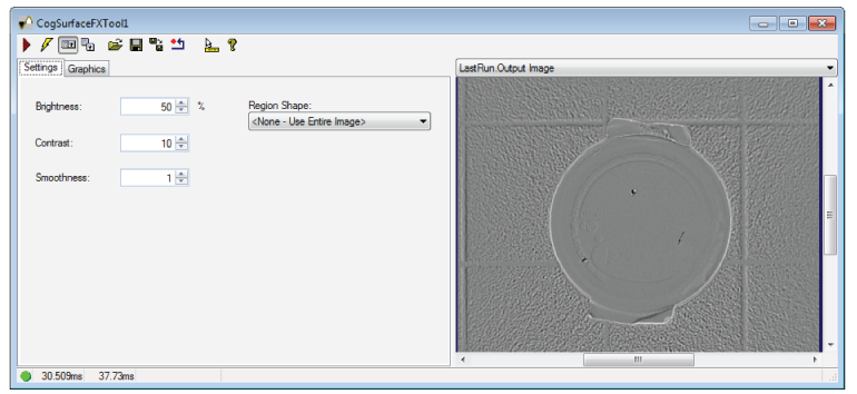
A SurfaceFX tool requires four separate input images of the object under inspection. See the topic Using a SurfaceFX Tool for more information on using a SurfaceFX tool. The following figure shows an example of the SurfaceFX tool edit control:
To include the edit control in your custom vision application, you must first add it to your Visual Studio .NET development environment. See the topic Adding Edit Controls to Visual Studio for more information.
See the following sections for more information:

The following table describes the function of each button:
| Button | Description | Function |
 | Run | Generate the output image using the four input images held by the InputVisionData. |
 | Electric mode | Toggle electric mode, where the SurfaceFX tool executes automatically when particular configuration parameters change. In electric mode, a lightning bolt appears next to every electric property. |
 | Local image display | Open or close the local image display window. A SurfaceFX tool supports the following image buffers:
|
 | Floating image display | Open a floating image window, which supports the same image buffers as the local image display window. |
 | Open | Open a VisionPro persistence (.vpp) file that contains a set of saved properties for this vision tool object type. VisionPro reports an error if you try to open a .vpp file for another object type. |
 | Save | Save the current properties of the vision tool to a VisionPro persistence (.vpp) file. The edit control allows you to choose between saving the vision tool with or without its image buffers and tool results. |
 | Save As | Save the current properties of the vision tool to a new VisionPro persistence (.vpp) file. |
 | Reset | Reset the vision tool to its default state. The tool gives you a choice between resetting to the default-constructed state, which is appropriate when you are using it in a Visual Studio.NET application, and its template-initialized state, which is appropriate for QuickBuild applications. |
 | Show ToolTips | Enable or disable the display of tooltips for individual items in the edit control. |
 | Help | Open this VisionPro online help file. |
Use the Settings tab to specify the qualities of the output image. The following figure shows the default Settings tab:
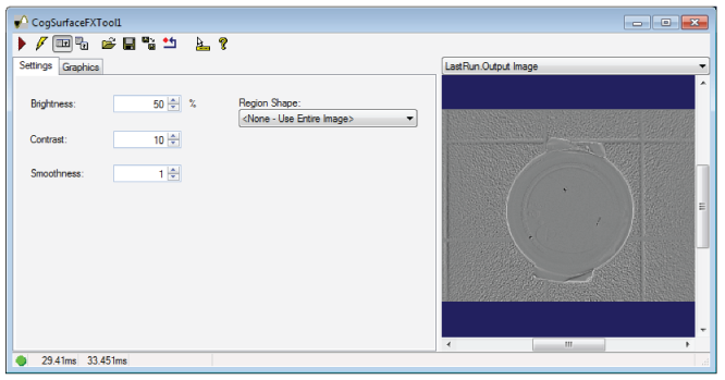
The Settings tab offers the following controls:
| Control | Description |
| Brightness | Set the brightness percentage for flat areas of the CogImage8Grey output image. For example, a percentage of 50% is equal to a grey value of 128, while a percentage of 100% is equal to a grey value of 255. |
| Contrast | Set the contrast for the CogImage8Grey output image, where higher values increase the intensity difference between pixels in the output image. |
| Smoothness | Set a value to control a smoothing filter applied to the grey levels of the output image. Larger values increase the appearance of larger defects, while smaller values increase the appearance of smaller defects. |
Region | Select the shape of the input region that specifies the portion of each image to be processed. Selecting None=Use entire image means that the tool uses the entire input image. An SurfaceFX tool supports the following input region shapes:
The set of region-defining parameters that appear depend on the region shape you use. |
| SelectedSpaceName | The coordinate space in which the SurfaceFX tool is interpreted. For more information, see Coordinate Space Names. |
Experiment with these parameters to get the best results for your vision application.
Use the Graphics tab to select the shape of the input region. The following figure shows the Graphics tab:
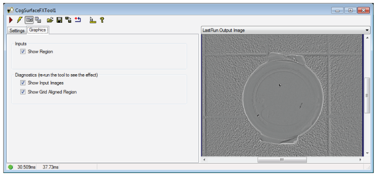
Use the following options to configure the input region:
| Control | Description |
| Show Region | Show the input region on each of the Current and LastRun images. |
Select which diagnostic data the tool stores in the LastRunRecord
|