This topic contains the following sections.
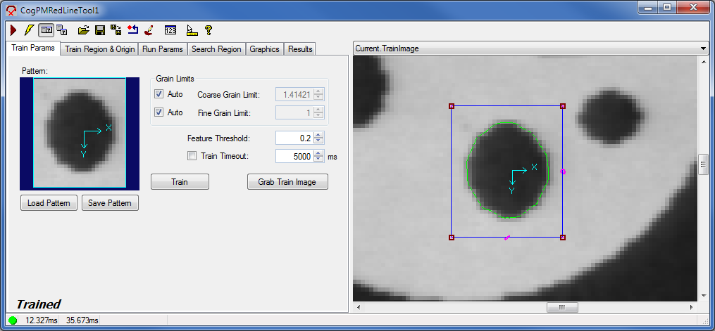
The CogPMRedLine tool edit control provides a graphical user interface to the CogPMRedLineTool tool, which you use to train a pattern and then have the tool search for it in successive input images. You create the trained pattern from an image. The pattern search can be constrained by an optional search region within the input image. The following figure shows an example CogPMRedLine tool edit control:
See the topic PatMax RedLine Tool for more information on the CogPMRedLine tool.
The PMRedLine edit control includes the following components:
- A row of control buttons at the top left.
- A tool display window that can display the PMRedLine tool image buffers: Current.TrainImage, Current.InputImage, and LastRun.InputImage. These buffers contain the trained pattern, the search image in which the PMRedLine tool searches for the pattern, and the same image with the results of the search. Right click the tool display to bring up menu options that include zooming in or out of the image or showing a pixel or subpixel grid.
- A set of tabs organized by function. These functions include parameter settings to run the tool, parameter settings for the search region of interest, display settings for the tool displays, and training results. Pressing the Control + Tab keys scrolls through the set of tabs.
- A status bar at the bottom left of the control. A green circle indicates that the tool ran successfully; red means the tool ran unsuccessfully. The status bar also displays the time to run the tool and any error codes or messages. The first time that the status bar displays is the raw tool execution time. The second includes the time needed to update the edit control.

The following table describes the functions of the buttons at the top left of the control.
| Button | Description |
 | Run the PMRedLine tool. You must have a trained pattern, an input image, and specified run parameters. The PMRedLine tool searches for the trained pattern in the input image. You may constrain the pattern search to a search region within the input image. |
 | Toggles electric mode. When selected, the PMRedLine tool runs automatically if certain parameters have changed. These parameters are indicated by electric bolt icons that appear when the tool is in electric mode. |
 | Opens the local tool display window, which can display the Current.InputImage, Current.TrainImage, or LastRun.InputImage buffer. |
 | Opens one or more floating tool display windows. You can display the Current.InputImage, Current.TrainImage, or LastRun.InputImage buffer. Unlike the local tool display, you can resize or move the position of the floating tool display window. |
 | Loads a VisionPro persistence (.vpp) file, which contains a set of saved properties for this vision tool object type. Loading a persistence file for another object type throws an error and the load is unsuccessful. For more information about VisionPro persistence features, see the topic Persistence in VisionPro. |
 | Saves the current properties of the underlying tool to a VisionPro persistence file. You have the option to save either the entire tool or the tool without its images or results. |
 | Saves the current properties of the underlying tool to a new VisionPro persistence file. |
 | Resets the underlying tool to a default state. |
 | Opens the Image Mask Editor for creating a mask to add to the training image. |
 | Opens a new, separate results window, allowing you to view run results without turning to the Results tab. |
 | Enables or disables the display of tooltips for individual items in this edit control. |
 | Access the VisionPro Software Documentation. |
The PMRedLine edit control has three image buffers. Two of the buffers use the underlying PMRedLine tool's InputImage and TrainImage; the third buffer displays the last input image that the PMRedLine tool ran on and the results of that search. All three buffers can be shown in both the local and floating tool display windows.
- The Current.InputImage provides the input images to the PMRedLine tool.
- The Current.TrainImage contains the training image.
- The LastRun.InputImage buffer displays the last image on which the tool most recently ran. Use the Graphics tab to highlight the search area and the results of the search.
When you run the PMRedLine tool, the tool searches the Current.InputImage for the pattern in the Current.TrainImage buffer, and stores the results of this search on the Results tab.
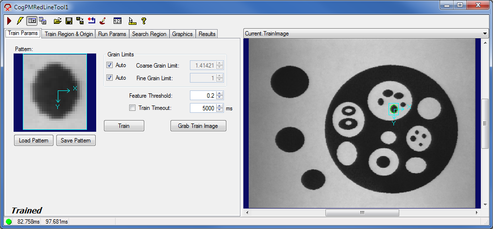
Use the Train Params tab to set training parameters and to train the search pattern.
| Feature | Description |
| Pattern | Displays the trained pattern, created from an image. This is specified by the TrainRegion, which is highlighted by a blue border, within TrainImage. You can set the train region using the Train Region and Origin tab or by resizing its display in Current.TrainImage. The message text at the bottom of the tab indicates whether the PMRedLine tool is trained. |
| LoadObjectFromFile | Opens a VisionPro persistence file, which has a VPP extension, that contains a trained pattern. |
| SaveObjectToFile | Saves the current trained pattern into a VisionPro persistence file, which has a VPP extension. |
| Train | Trains the desired pattern as specified by the TrainRegion in the TrainImage. If the tool already has a trained pattern, then the tool will untrain and then retrain. When the pattern is successfully trained, the text at the bottom of the control says "Trained." |
Grab Train Image button | Copies the image in the InputImage buffer into the TrainImage buffer. This button is not enabled unless there is an image in Current.InputImage. |
| Grain Limits | If GrainLimitCoarseAutoSelect is not selected, then the GrainLimitCoarse grain limit that you supply is used. If GrainLimitFineAutoSelect is not selected, then the GrainLimitFine grain limit that you supply is used. |
| FeatureThreshold | Controls how many features are included in the trained pattern. Raising the threshold reduces the number of trained features. Only adjust this parameter after you have looked at your trained pattern and confirmed that you need more (or fewer) image features. Large values (0.7 or higher) may produce too few features for accurate pattern finding. Large values may also eliminate so many features that it is impossible to even train a pattern. If you change this value on a trained pattern object, the pattern will become untrained. |
| TrainTimeout | The maximum execution time (in milliseconds) allowed for a PatMax RedLine tool to train. This value only applies if TrainTimeoutEnabled is set to true. |
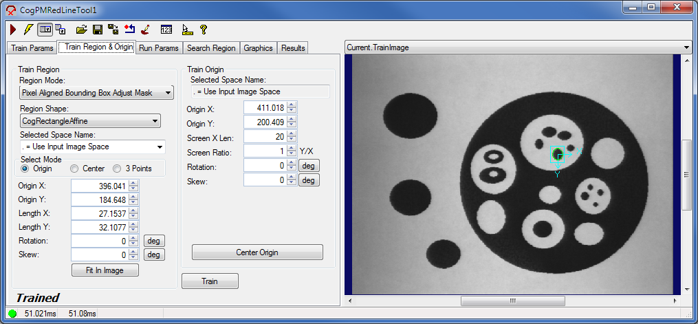
Use the Train Region and Origin tab to define the TrainRegion, which defines the area of the TrainImage buffer that becomes the trained pattern. You can also define the train region graphically in the Current.TrainImage buffer. It may be easier to first specify the training region graphically, then use this tab to fine tune the train region parameters. The PMRedLine edit control updates the train region values so that the values on this tab always match the shape of the train region in the Current.TrainImage buffer.
You can train the search pattern by clicking Train on this tab as well.
Some of the parameters on this tab, such as Rotation and Skew, can be specified in degrees (default) or radians. The underlying tool keeps the values in radians but the edit control converts them to degrees when appropriate.
| Feature | Description |
Defines the bounding box for the region.
| |
Select the shape of the input region. Selecting None=Use entire image means that the tool uses the entire input image. A PMRedLine tool supports the following input region shapes:
The set of region-defining parameters that appear depend on the region shape you use. For more information on using a polygon as an input region, see the topic Using Polygon Input Regions. | |
| SelectedSpaceName | The coordinate space in which the training region is interpreted. For information, see Coordinate Space Names. |
| Select Mode | Available when Region Shape is cogRectangle or cogRectangleAffine. Selects the set of parameters that define the rectangle. If cogRectangleAffine is chosen, note that the angles of rotation and skew can be specified in degrees or radians, although the underlying tool keeps the measurements in radians. |
| FitToImage | Centers the train region within Current.TrainImage. |
| Feature | Description |
Origin X Origin Y Screen X Len Screen Ratio Rotation Skew | Values that define the location and orientation of the train region's origin. These values will change if you modify the origin graphically. Note that the angles of rotation and skew can be specified in degrees or radians. Equivalent to the Origin property. |
| Center Origin | Sets the train region's origin at the center of the train region. |
| Feature | Description |
| Train | Trains the desired pattern as specified by the TrainRegion in the TrainImage. If the tool already has a trained pattern, then the tool will untrain and then retrain. When the pattern is successfully trained, the text at the bottom of the control says "Trained." |
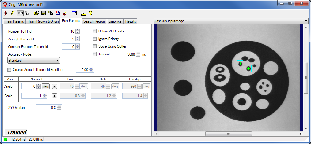
Use the Run Params tab to specify how to perform the pattern search. These parameters include the accuracy to use, thresholds, and the amount of rotating and scaling allowable during the pattern search.
| Feature | Description |
| NumberToFind | Sets the number of results to search for. You should set this value to the maximum number of pattern instances that you ever expect to find in your input image. If the ReturnAllResults run-time parameter is false, the number of results returned by the PMRedLine tool will always be less than or equal to the value you specify. If ReturnAllResults is true, you may get additional results. |
| AcceptThreshold | Sets the acceptance threshold for the score of a result. Only instances of the pattern that receive scores greater than or equal to this threshold are accepted. Valid range is from zero to one. You should supply an acceptance threshold that is lower than the lowest score you ever expect to receive from a true instance of your pattern. |
| ContrastFractionThreshold | Sets the threshold for the contrast fraction of a result. Only instances of the pattern that have a contrast fraction greater than or equal to this threshold are accepted. Valid range is from zero to one. It is computed by dividing the average contrast of the matching image features by the average contrast of the trained pattern features. If this ratio exceeds one, it is reported as exactly one. You can discard results with very low contrast (relative to the pattern) by setting the ContrastFractionThreshold. You should supply a non-zero value that is lower than the lowest contrast fraction you ever expect to receive from a true instance of your pattern. |
| AccuracyMode | Sets the desired level of accuracy for result poses. The PMRedLine tool may run faster if your application can tolerate lower accuracy. The accuracy of a result pose (including its position, rotation, and scale) is highly dependent upon the quality of the trained pattern and the contents of the runtime image. For most applications the Standard accuracy mode gives a good trade-off between accuracy and speed. If you desire more accuracy and are willing to sacrifice some speed, you can use the Accurate mode. If you desire more speed and are willing to sacrifice some accuracy, you can use the Fast mode. Fast mode is especially useful if you are searching for multiple pattern instances and only want to know how many were found. |
| CoarseAcceptThresholdFraction | Sets the fraction of the accept threshold that should be used to evaluate candidate scores during the coarse phase of the PMRedLine tool's run time. The PMRedLine tool first finds candidate patterns at coarse granularity. High-scoring coarse results are then refined at fine granularity. A coarse result is considered "high-scoring" if its score exceeds an internally-computed coarse accept threshold. By default, the PMRedLine tool determines the coarse accept threshold automatically. In exceptional cases you may need to override the automatic computation. You can override the automatic computation by setting CoarseAcceptThresholdFractionEnabled to true. The coarse accept threshold will then be computed by multiplying together the coarse accept threshold fraction, specified by this value, and the AcceptThreshold. |
| ReturnAllResults | Sets whether the PMRedLine tool should return only the results that you asked for or it should also return results that are similar to the ones you asked for. If the PMRedLine tool fails to return all of the results that you expect, it may be useful to set this property to true. This allows the PatMax RedLine tool to return additional results that are similar to the ones you asked for. Additional results will not always be present, but if they are present you can inspect them to see if the PatMax RedLine tool is finding your desired result and then excluding it from the final set of results because it fails to meet one of the acceptance conditions. You can then adjust the relevant acceptance condition so that the desired result is returned. |
| IgnorePolarity | Sets whether to ignore the polarity of edge features when searching for patterns. If true, the polarity of the pattern features is ignored. If false, only patterns whose polarity matches the trained pattern will be found. The polarity of a feature indicates whether the edge describes a light-to-dark transition in the image or a dark-to-light transition. You should ignore polarity if instances of your pattern may have edge features whose polarity is the opposite of the trained ones. In this case your pattern should receive approximately the same score regardless of whether some, all, or none of the features have opposite polarity. |
| ScoreUsingClutter | Sets whether the PMRedLine tool should reduce the score of results that contain extraneous features at the found image location. Extraneous features are known as clutter. They appear in the run-time image at locations which should be empty. A pattern's score is reduced as the amount of clutter increases, but the score will never go negative. A clutter measurement is computed, and reported in each result, only if ScoreUsingClutter is set to true. Otherwise, each result reports a clutter value of -1. The clutter value is a ratio. It is computed by dividing the number of clutter features at the found location by the number of features in the trained pattern. This ratio can be larger than one. Clutter features are extra features that appear in the run-time image at locations which should be empty. The corresponding area of the train image is called "empty" when: it lies within the train region, it contains no features, and it is not masked as "Don't Care". |
| Timeout | Sets the maximum execution time (in milliseconds) allowed for a PMRedLine tool to run. This value only applies if TimeoutEnabled is set to true. |
| ZoneAngle | Specifies the angle of rotation that is allowable when the PMRedLine tool performs a pattern search. You can specify a nominal value that the PMRedLine results must match exactly or you can click the
 |
| ZoneScale | Specifies the scale value that is allowable when the PMRedLine tool performs a pattern search. You can specify a nominal value that the PMRedLine results must match exactly or you can click the
|
| XYOverlap | Sets the area overlap threshold. Two result candidates are said to overlap in area if the fraction of their area that overlaps is greater than the given XYOverlap threshold. The valid range of the threshold is from zero to one. The PMRedLine tool discards the weaker pattern instance when two pattern instances overlap for all degrees of freedom (DOF) as well as area. See the Overlap property of the angle DOF zone and the Overlap property of the scale DOF zone for more information. |
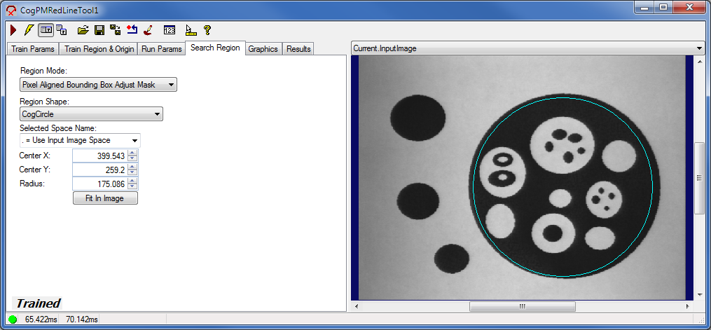
Use the Search Region tab to define the SearchRegionMode, the area of the InputImage buffer to which the pattern search is constrained. The search region appears with a blue border in the Current.InputImage, and you can graphically define the search region in this buffer. It may be easier to specify the search region graphically, then use this tab to fine tune the search region parameters. When you resize the search region in the InputImage, the values on this tab change; likewise, changing the parameter values causes the search region to alter its size and shape.
| Feature | Description |
Defines the bounding box for the region.
| |
| SearchRegion | The shape of the search region. Selecting "None=Use entire image" means that the entire Current.InputImage becomes the search region. The set of region-defining parameters depends on the selected Region Shape. |
| SelectedSpaceName | The coordinate space in which the search region is interpreted. For more information, see Coordinate Space Names. |
| Select Mode | Available when Region Shape is cogRectangle or cogRectangleAffine. Selects the set of parameters that define the rectangle. If cogRectangleAffine is chosen, note that the angles of rotation and skew can be specified in degrees or radians, although the underlying tool keeps the measurements in radians. |
| FitToImage | Centers the search region within Current.InputImage. |
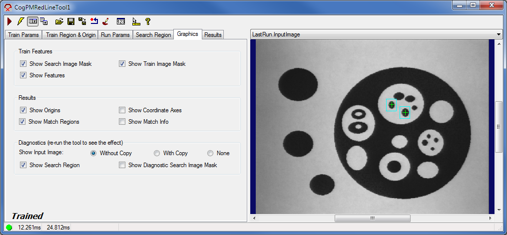
Use the Graphics tab to choose the results graphics that are displayed in the LastRun.InputImage display.
| Feature | Description |
Train feature display | You can show these features in the Current.TrainImage buffer, which contains the trained pattern:
The preceding features appear only if the pattern is trained successfully.
|
Result graphics display | You can show these features in the LastRun.InputImage buffer, which contains the image that the PMRedLine tool last searched, and the results of that search. Uses the CreateResultGraphics method to generate these results.
|
Diagnostics display | Displays the following features in the LastRun.InputImage buffer. Uses the CreateResultGraphics method to generate these results.
The Show Input Image option buttons let you specify whether a reference to the input image or a deep copy of the input image is displayed for the LastRun.InputImage. You can also specify that no image be displayed. |
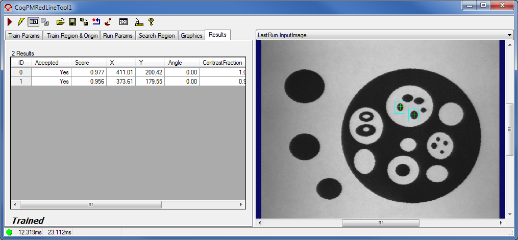
The Results tab displays the results of the most recent pattern searches. This corresponds to the CogPMRedLineResult interface. Use the slider control below the results grid to display the complete set of results.
| Feature | Description |
Results Grid | Displays the following information for each result.
The coordinates, angle, and scaling factor are retrieved with the GetPose method.
|