This topic contains the following sections.
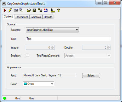
The CogCreateGraphicLabel tool edit control provides a graphical user interface to the CogCreateGraphicLabelTool, which you use to add a CogGraphicLabel to the output record of your CogToolGroup or CogToolBlock. See the topic Creating a Graphic Label for details on using a CogCreateGraphicLabel tool. The following figure shows an example CogCreateGraphicLabel edit control:
The edit control offers the following features:
- A row of control buttons at the top left
- A set of function tabs to define which data to display, its placement, and in the desired size, font and color
- An image display window for displaying tool images and the desired textual graphics
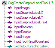
Use QuickBuild to create a CogCreateGraphicLabel tool. A new CogCreateGraphicLabel tool appears with input terminals for the InputImage and a variety of potential input values generated by other vision tools in the tool group or tool block, as shown:
To include the edit control in your custom vision application, you must first add it to your Visual Studio .NET development environment. See the topic Adding Edit Controls to Visual Studio for more information.

The following table describes the function of each button:
| Button | Description | Function |
 | Run | Applies the textual graphics to the image display and adds it to the output record. |
 | Electric mode | Toggle electric mode, where the CogCreateGraphicLabel tool executes automatically when particular configuration parameters change. In electric mode, a lightning bolt appears next to every electric property. |
 | Local image display | Open or close the local image display window. A CogCreateGraphicLabel tool supports the following image buffers:
|
 | Floating image display | Open one or more floating image windows, which support the same image buffers as the local image display window. |
 | Open | Open a VisionPro persistence (.vpp) file that contains a set of saved properties for this vision tool object type. VisionPro reports an error if you try to open a .vpp file for another object type. |
 | Save | Save the current properties of the vision tool to a VisionPro persistence (.vpp) file. The edit control allows you to choose between saving the vision tool with or without its image buffers and tool results. |
 | Save As | Save the current properties of the vision tool to a new VisionPro persistence (.vpp) file. |
 | Reset | Reset the vision tool to its default state. The tool gives you a choice between resetting to the default-constructed state, which is appropriate when you are using it in a Visual Studio.NET application, or its template-initialized state, which is appropriate for QuickBuild applications. |
 | Show ToolTips | Enable or disable the display of tooltips for individual items in the edit control. |
 | Help | Open this VisionPro online help file. |
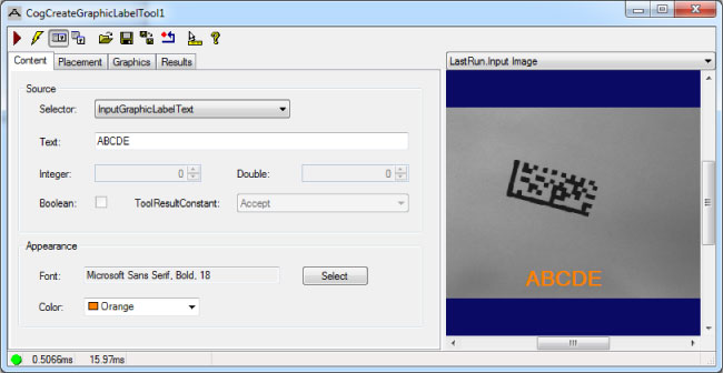
Use the Contents tab to determine the contents and appearance of the textual graphics. The following figure shows an example Contents tab:
Set the following parameters to select the source and content of the textual graphics.
| Parameter | API | Description |
Selector | Determine which field or fields are available for display in the text string. The options are:
| |
| Text | Text | Set the static or formatted string to display. |
| Integer | InputInteger | View the integer value supplied to the CogCreateGraphicLabel tool or set a static value as your application requires. |
| Double | InputDouble | View the double-precision floating point value supplied to the CogCreateGraphicLabel tool or set a static value as your application requires. |
| Boolean | InputBoolean | View the Boolean value supplied to the tool or check the box to display the string "True" in the output string. |
| ToolResultConstant | InputToolResultConstant | View the CogToolResultConstants property supplied to the tool or set a static value as your application requires. |
Use the Font and Color properties to determine the appearance of the output string.
Use the Placement tab to determine the location of the bounding box containing the CogGraphicLabel. The following figure shows an example Placement tab:
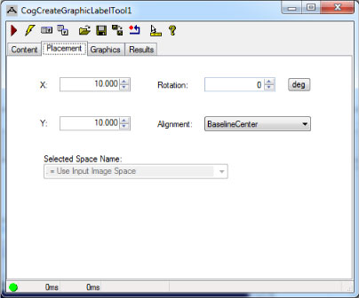
The tab offers the following parameters
| Parameter | API | Description |
| X | X | The x-coordinate for the origin of the graphic label. |
| Y | Y | The y-coordinate for the origin of the graphic label. |
Rotation | The angle (in radians or degrees, from the x-axis) of the text label. Click deg to swtich between degrees and radians. | |
| Alignment | Alignment | Control the alignment of the text field in relation to its (x, y) anchor point. See the topic Creating a Graphic Label for more information on specifying an alignment. |
| Selected Space Name | SelectedSpaceName | Coordinate space in which this shape is to be interpreted. |
Use the Graphics tab to select diagnostic graphic options associated with the LastRun.Input Image buffer:
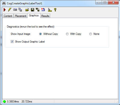
The Without Copy, With Copy, and None options determine whether or not the input image is recorded as part of the diagnostic record; and whether the image is copied to the record or saved in the record as a reference.
Disable the Show Output Graphic Label option to disable the display of the textual graphics.
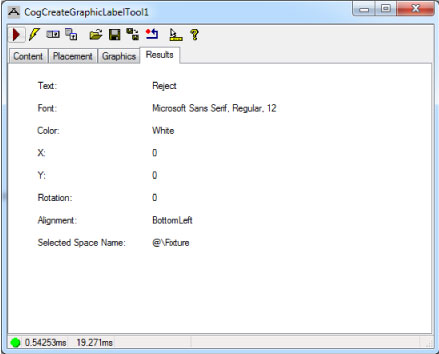
The Results tab displays the current settings for the tool, as shown in the following example: