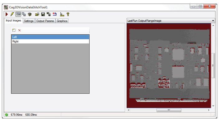
The Cog3DVisionDataStitch edit control provides a graphical user interface to the Cog3DVisionDataStitch tool, which you use to combine the 3D range images from separate 3D sensors. The following figure shows an example Cog3DVisionDataStitch tool edit control:
See the topic Image Stitching for more information on the Cog3DVisionDataStitch tool.
Cognex recommends you use Cognex Designer to create your 3D application to analyze stitched images. Contact your Cognex sales representative for more information on Cognex Designer.
For a Designer sample application that performs image stitching, see www.cognex.com/CognexDesignerSamples.
To include the edit control in your custom vision application, you must first add it to your Visual Studio .NET development environment. See the topic Adding Edit Controls to Visual Studio for more information.
This topic contains the following sections.
The Cog3DVisionDataStitch tool supports the following buttons along the top of the edit control:

| Button | Description | Function |
 | Run | Perform the stitching on the supplied vision data. |
 | Electric mode | Toggle electric mode, where the tool executes automatically when you change the value of select parameters. In electric mode, a lightning bolt appears next to every electric property. |
 | Local image display | Open or close the local image display window. A Cog3DVisionDataStitch tool supports the following image buffers:
|
 | Floating image display | Open one or more floating image windows, which support the same image buffers as the local image display window. |
 | 3D Display | Open a 3D Viewer displaying the rerendered 3D range image. See the topic Viewing 3D Range Images with the 3D Viewer for more information on using the 3D Viewer. |
 | Open | Open a VisionPro persistence (.vpp) file that contains a set of saved properties for a Cog3DVisionDataStitch tool. VisionPro reports an error if you try to open a .vpp file for another tool type. |
 | Save | Save the current properties of the Cog3DVisionDataStitch tool to a VisionPro persistence (.vpp) file. The edit control allows you to choose between saving the vision tool with or without its image buffers and tool results. |
 | Save As | Save the current properties of the vision tool to a new VisionPro persistence (.vpp) file. |
 | Reset | Reset the vision tool to its default state. This tool gives you a choice between resetting to the default-constructed state, which is appropriate when you are using it in a Visual Studio.NET application, and its template-initialized state, which is appropriate for QuickBuild applications. |
 | Show ToolTips | Enable or disable the display of tooltips for individual items in the edit control. |
 | Help | Open this VisionPro Software Documentation file. |
Use the Input Images tab to build input CogVisionDataContainer this tool will use to specify the 3D range images it will stitch. The following figure shows the Input Images tab:
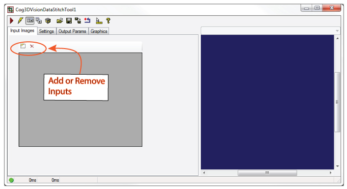
Every input accepts either a 3D range image or a CogVisionDataContainer storing a 3D range image and 16-bit greyscale data from the same scan.
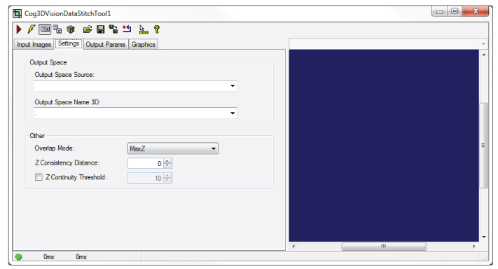
Use the Settings tab to define the space you want to use to render the stitched image and configure how to handle pixels from adjacent 3D range images that overlap. The following figure shows the Settings tab:
| Parameter | Description |
| Output Space Source | The dictionary key of the input range image whose 3D coordinate space tree holds the desired output space. In the case of input range / greyscale image pairs, this is the key of the nested container that in turn holds the range image whose 3D coordinate space tree holds the desired output space. |
| Output Space Name 3D | The name of the 3D space in which the output range image will be rendered. |
Overlap Mode | How input pixels that overlap in X and Y will be processed to produce an output pixel value:
|
Z Consistency Distance | The maximum Z difference in client space over which overlapping pixel values will be averaged. If Overlap Mode is set to MaxZ, then overlapping pixels whose height is within this distance of the maximum height at that location will be averaged. If Overlap Mode is set to MinZ, then overlapping pixels whose height is within this distance of the minimum height at that location will be averaged. Overlapping pixel height values that are outside the specified range will be ignored. If Overlap Mode is any other value, this parameter is ignored. |
| Z Continuity Threshold | Specifies a Z height difference in mm. The stitched image will not interpolate between sensed Z values which differ by more than the this value. |
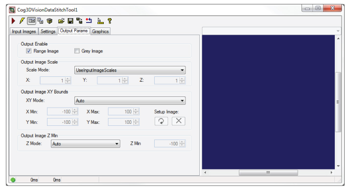
Use the Output Params tab to control how the Cog3DVisionDataStitch tool renders the output stitched image. The following figure shows a Output Params tab:
| Parameter | Description |
Output Enable | Select whether you want to generate a stitched 3D range image, a stitched 16-bit greyscale image, or both. Be aware you must supply the Cog3DVisionDataStitch tool with nested CogVisionDataContainers to generate a stitched grey image. |
Scale Mode | How to scale the output range image. This controls the resolution of the output range image. The options are:
|
XY Mode | How to define the X, Y bounds of the output image. The options are:
|
Z Mode | Defines how to handle the Z values of the output range image. The options are:
|
Use the Graphics tab to control how the Cog3DVisionDataStitch tool renders the output stitched image. The following figure shows a Output Params tab:
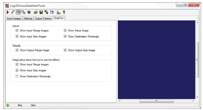
| Parameter | Description |
| Inputs | Specify which input images and graphics are made available in the Current.InputImage buffer. |
| Results | Specify which output images and graphics are made available in the LastRun.InputImage buffer. |
| Diagnostics | Specify which images and graphics are recorded as part of the diagnostic record. |