This topic contains the following sections.
The Linescan Distortion Correction Tool edit control provides a graphical user interface to the CogLinescanDistortionCorrectionTool tool, which you use to correct nonlinear optical distortion in an image acquired from a line scan camera. The following figure shows the Linescan Distortion Correction Tool edit control:
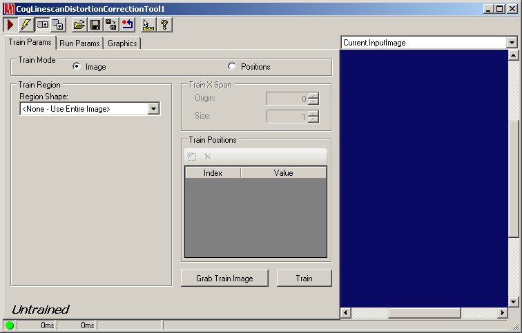
The edit control allows you to perform the following actions:
- Train the tool using an input image.
- Train the tool using a collection of 1D positions.
- Specify the training and run-time regions.
- Run the tool and view the undistorted image as well as diagnostic information.
If you add a Linescan Distortion Correction tool to a QuickBuild Job, it appears with terminals for the input and output images, as shown in the following figure:
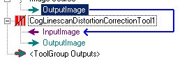
See the topic Adding Edit Controls to Visual Studio for details on how to add a Linescan Distortion Correction tool edit control to your Visual Studio.NET development environment if you are creating a vision application using the VisionPro application programming interface (API). The QuickBuild development environment supports the Linescan Distortion Correction tool edit control automatically.

The following table describes the function of each button:
| Button | Description | Function |
 | Run | Create an undistorted image, based on the current training parameters. |
 | Electric mode | Toggle electric mode, where the Linescan Distortion Correction tool executes automatically when particular configuration parameters change. In electric mode, a lightning bolt appears next to every electric property. |
 | Local image display | Open or close the local image display window. A Linescan Distortion Correction tool supports the following image buffers:
|
 | Floating image display | Open one or more floating image windows, which support the same image buffers as the local image display window. |
 | Open | Open a VisionPro persistence (.vpp) file that contains a set of saved properties for this vision tool object type. VisionPro reports an error if you try to open a .vpp file for another object type. |
 | Save | Save the current properties of the Linescan Distortion Correction tool to a VisionPro persistence (.vpp) file. The edit control allows you to choose between saving the Linescan Distortion Correction tool with or without its image buffers and tool results. |
 | Save As | Save the current properties of the vision tool to a new VisionPro persistence (.vpp) file. |
 | Reset | Reset the vision tool to its default state. The tool gives you a choice between resetting to the default-constructed state, which is appropriate when you are using it in a Visual Studio.NET application, or its template-initialized state, which is appropriate for QuickBuild applications. |
 | Show ToolTips | Enable or disable the display of tooltips for individual items in the edit control. |
 | Help | Open this VisionPro online help file. |
The edit control contains the following controls:
| Parameter | Description |
| TrainMode | Specify Image to train the tool using an acquired image. The image must be acquired using the run-time optics, but without any motion. Specify Positions to train the tool by providing the image x-offsets of a series of equally spaced physical points. |
If you have specified Image for the Train Mode, you can specify the region of the training image to use for training. The run-time image input region must fit within the training region. This value is ignored for Position training. The tool is untrained when any aspect of the region changes, regardless of the training mode. | |
If you have specified Position for the Train Mode, use these controls to specify the offset and size of the image coordinate space to train. The values are interpreted in the selected space of the run-time image. The run-time image input region must fit within the trained X-span. This value is ignored for Image training. The tool is untrained when either of these values changes, regardless of the training mode. | |
AddTrainPosition | Use this control to add, modify, or delete the positions used for Position-based training. The rows in the table control correspond to evenly spaced physical positions extendeding across the run-time image field of view. The Value for each row is the image x-coordinate that for the position. The Values must increase with each additional row. These values are ignored for Image training. The tool is untrained whenever a position is added, deleted, or its value chaged, regardless of the training mode. |
| TrainImage | Copies the current value of the tool's Current.InputImage image buffer to the tool's training image. The button is provided as a convenient method for setting the training image without needing to create a dedicated input terminal. |
| Train | Trains the tool using the current training image and region (for image training) or position parameters (for position training). |
Use the Run Params tab to specify the region of the run-time image to correct.
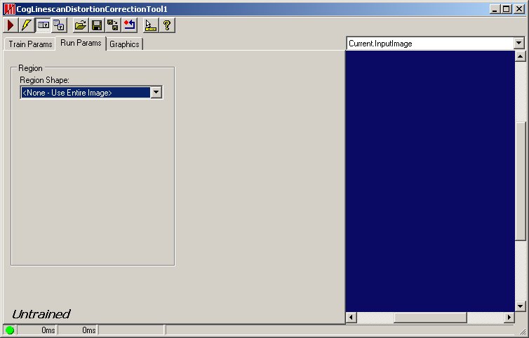
Use the Region tab to specify the type of region you want to use to examine the run-time image. By default, the region of interest is configured to encompass the entire input image, but some applications might examine just a portion of each acquired image.
Use the following controls to configure the region of interest:
| Feature | Description |
Select the shape of the input region. Selecting "None=Use entire image" means that the tool uses the entire input image. A Line Scan Distortion Correction tool supports the following input region shapes:
Regardless of the region type, the tool uses the pixel-aligned bounding box of the region. | |
| SelectedSpaceName | The coordinate space in which the region is interpreted. For more information, see Coordinate Space Names. |
| Select Mode | Available when Region Shape is CogRectangle or CogRectangleAffine. Selects the set of parameters that define the rectangle. If cogRectangleAffine is chosen, note that the angles of rotation and skew can be specified in degrees or radians, although the underlying tool keeps the measurements in radians. |
| FitToImage | Centers the copy region within Current.InputImage. |
Use the Graphics tab to control what graphics and images the tool can display. Enabling more options can affect the time the tool requires to execute. The following figure shows a sample Graphics tab:
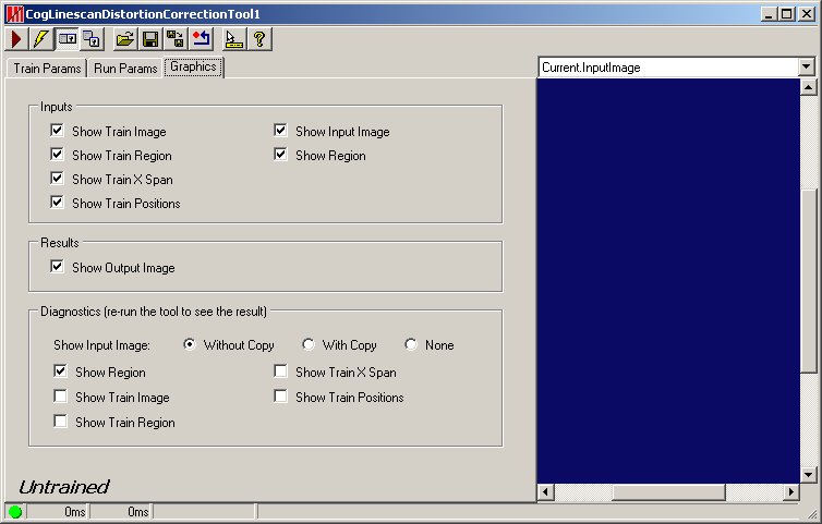
The tab contains a number of options:
| Parameter | Description |
| Inputs | Enable which input parameter graphics to show. |
| Results | Enable the image options you want the edit control to display. |
Diagnostics | For Show Input Image, determine whether or not the input image is recorded as part of the diagnostic record, and whether the image is copied to the record or saved in the record as a reference. Check Show Region to enable a graphic on the LastRun.InputImage corresponding to the region of interest. |