This topic contains the following sections.
The CogLinescanDistortionCorrectionTool allows you to rectify an image that contains nonlinear distortion in the x-axis direction. This is similar to the type of image rectification that the CogCalibCheckerboardTool can perform on images from line scan cameras.
This illustration shows the type of distortion that this tool can correct:

The key differences between the Checkerboard Calibration tool and the Linescan Distortion Correction tool are
- The Linescan Distortion Correction tool uses a simple training target that is placed at a fixed position in front of the camera (the Checkerboard Calibration tool requires that a calibration plate be moved relative to the camera).
- The Linescan Distortion Correction tool does not perform any calibration; no calibrated space is added to the image coordinate space tree (the Checkerboard Calibration tool computes a calibrated physical coordinate space and adds it to the image's coordinate space tree).
- The Linescan Distortion Correction tool does not rectify distortion caused by a camera that is rotated; it can only correct nonlinear optical and perspective distortion (the Checkerboard Calibration tool does rectify the image skew caused by a rotated camera).
In general, you should use the Checkerboard Calibration tool, as it provides the most accurate distortion correction and it provides calibration in addition to distortion correction. The Linescan Distortion Correction tool is intended to be used in applications where it is impossible to use a moving calibration plate.
The Linescan Distortion Correction tool has both a training phase and a run-time phase. Before you can use the tool to correct distortion in run-time images, you must train the tool using a training target that meets these requirements:
- It must be large enough to fill the entire field of view of your camera when it is placed at the working distance used by your application.
-
The surface of the target must have a series of alternating, equally sized white and black regions where
- The difference in grey levels in an image of the target must exceed 10.
- The regions should be sized so that at least 30 sets of black and white regions are visible across the camera's field of view.
- The black and white regions must be of equal width.
- In the acquired image of the target, each black and white region must be at least 10 pixels wide.
- The boundaries between the black and white regions must be parallel.
- It must be constructed so that it can be rigidly mounted at the working distance of your application such that the points defined by the intersection of a line normal to the direction of travel with the boundaries between dark and light regions are collinear; the target must be flat in the x-direction.
The following figure shows a valid training target:
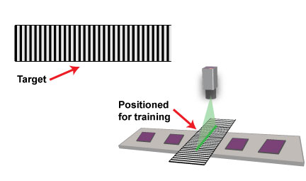
To train the Linescan Distortion Correction tool, you must follow these steps:
- Mount your camera in the location where it will be used at run time. Adjust your focus, lighting, and aperture to meet the requirements of your application. Note: You cannot change the physical or optical characteristics of the camera after training.
- Place the training target such that the camera field of view is filled by the target, the boundaries between the black and white regions are parallel to the direction of travel, and the surface of the target is at the same height as the parts or surface being inspected.
- Without moving the target acquire an image with at least 50 scan lines.
The acquired image should appear to contain a series of alternating dark and light stripes.
Note: The simplest method for acquiring the training image is to temporarily enable the test encoder, specify an ROI height of 50, and then acquire an image.
- Set the TrainImage to be the acquired image, then call Train.
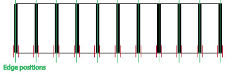
The following figure provides an overview of the training process:

In addition to using image-based training, the Linescan Distortion Correction tool also allows you to train the tool using synthetic data. To perform synthetic training, you supply a set of X-offsets, where the offsets are the set of image locations that correspond to a set of evenly spaced physical positions on the plane being inspected.
If you use position-based training, you must determine the image coordinate X-offset positions that correspond to evenly spaced locations in the physical world.
Position-based training may be needed is if your application requires the use of a training target that does not conform to the requirements for image-based training targets. For example, suppose that your application used a training target that consisted of equally spaced dark bars on a light background, but the bars were narrower than the light spaces between bars:

While this target does contain evenly spaced features, since the size of the dark bars does not match the size of the light regions between bars it cannot be used for image-based training, which requires equally sized dark and light bars.
To use an image of this target with position-based training, you would configure a caliper tool to find edge pairs, where the left edge had a negative (light-to-dark) polarity and the right edge had a positive (dark-to-light) polarity. When configured to search for edge pairs, the caliper tool returns the location of the center point of the pair. In this case, the center point corresponds to the center point of the bar.
Note: Unlike image-based training, there is no requirement to acquire multiple image lines for training. For best results, however, Cognex recommends that you acquire multiple image lines before running the Caliper tool.
To train the Linescan Distortion Correction Tool using position-based training, simply provide the edge pair position results, in order, to the tool.
To run a trained Linescan Distortion Correction tool, simply supply a run-time image from the line scan camera used to generate the training image as the input image and run the tool. The supplied image must be the same width as the training image, but it may be of any height.
Note: If a subregion was used to train the tool, then a subregion with the same width and x-offset must be applied to the run-time images.