You may have one or more computer-aided design (CAD) drawings that you want to pass to VisionPro as a 3D range image for analysis by the 3D vision tools that VisionPro supports. Your VisionPro installation includes the Cognex 3D CAD Import Tool, which you use to convert a CAD file into a 3D range image. The tool creates the 3D range image based on the surface region shown in the display:
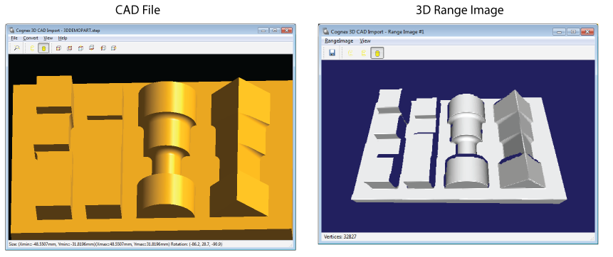
Launch the Cognex 3D CAD Import Tool by choosing Start->All Programs->Cognex->VisionPro->Utilities->CAD Import Tool. The tool includes its own help file for more information.
While the 3D CAD Import Tool converts single CAD images to 3D range images quickly, it does not support a programming interface. This prevents you from converting a library of CAD files without opening each file successively, or from retraining a vision application as it executes by converting the appropriate CAD file and using the 3D range image it generates with the existing 3D vision tools already configured. VisionPro offers a separate programming interface for working with CAD files apart from the 3D CAD Import Tool.
See the following sections for more information:
VisionPro supports the CogCADToRange class to programatically open a CAD file and render the shape into a 3D range image from a user-specified point of view.
- The class supports the STEP and IGES CAD formats.
The class can be used from both:
- A .NET application
- A scripting CogToolBlock in QuickBuild.
The API generates a CogCADToRangeResult object containing the 3D range image and other data about the rendering process.
Note: Be aware the rendering process is lengthy and CPU extensive. Cognex recommends you enable multithreading and choose a sub-set of CPUs available for best performance.
The transforms that allow CogCADToRange to convert a CAD file into a 3D range image reference a number of coordinate spaces you should be familiar with to use the API effectively:
CAD3D: The coordinate space used by the CAD file.
CAD3D space is assumed to be right-handed, and its origin is implicitly specified in the CAD file and located anywhere. The coordinates are assumed to be in millimeters.
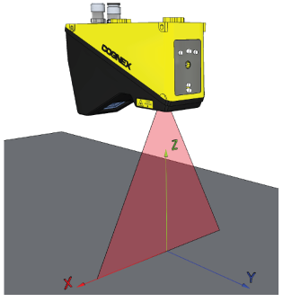
Image3D: The coordinate space of the root space (a.k.a @) in the 3D range image.
Image3D space is left-handed where the x-axis goes to the right, the y-axis goes to the bottom and the z-axis comes out of the (x,y) plane towards the viewer. The origin is the top-left corner of the range image and the coordinates are specified in pixels:
Projection3D: An intermediate coordinate space where the orthographic projection occurs.
Projection3D space has the same handedness and origin as CAD3D space. The z-axis is aligned with the viewing direction and pointed towards the viewer.
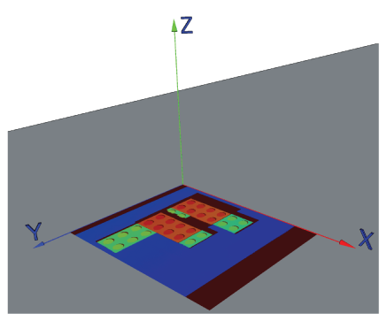
Sensor3D: The default coordinate space of the 3D range image.
Sensor3D space is right-handed where the x-axis goes to the right, the y-axis goes to the top and the z-axis comes out of the (x,y) plane towards the viewer. The origin is in the bottom middle of the 3D range image. The coordinates are specified in millimeters:
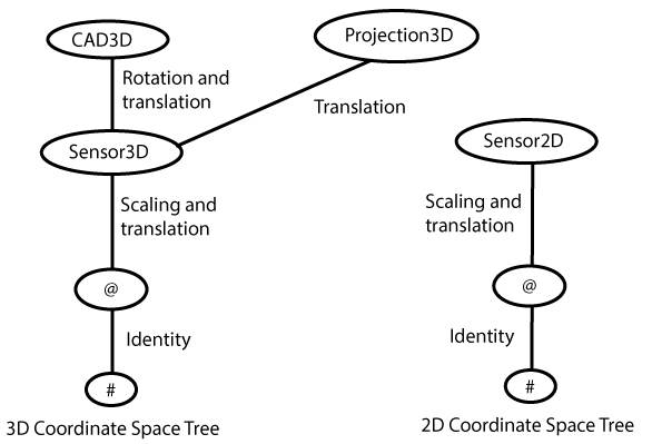
The following diagram represents the coordinate space trees in the resulting 3D range image:
More on the 3D transforms:
- RootFromSensor3DTransform has a diagonal matrix based off the scaling factors, and the translation holds the offset between Image3D and Sensor3D.
- Sensor3DFromCAD3DTransform is a rotation transform and the translation between the Sensor3D and CAD3D origin.
- Sensor3DFromProjection3DTransform holds just a translation between Sensor3D and CAD3D origin.
More on the 2D transform:
- RootFromSensor2DTransform has a the diagonal matrix based off the scaling factors, and the translation holds the offset between Root and Sensor2D.
A CogCADToRange object requires the following parameters to perform the rendering operation.
- FileName: The name of the CAD file you want to convert.
- ScaleX, ScaleY, and ScaleZ: The scaling factors along the (X,Y,Z) axes in the Sensor3D space, specifying the millimeter to pixel conversion.
Projection3DFromCAD3DTransform: The 3D rotation transform that can be used to map the shape in the CAD file to the 3D range image.
You can set the transform explicitly or it can be computed internally from the ViewingDirection you specify.
- ViewingDirection: A Cog3DVect3 that holds the 3D viewing direction specified in CAD3D space.
- RotationMode: Specifies which property to use for the rendering operation, either Projection3DFromCAD3DTransform or ViewingDirection.
- Region: A Cog3DBox that defines the portion of the CAD file to render.
- Timeout: A maximum execution time allowed to render the 3D range image.
The resulting CogCADToRangeResult object contains the following properties:
- RangeImage: The CogImage16Range produced by the rendering operation.
OverflowOccurred: Indicates whether an overflow occured during the rendering operation.
An overflow occurs when mapping a z-value from the CAD to a 16-bit integer for the 3D range image. Overflow is handled by clamping the z-value to 65535, if necessary. Underflow cannot occur because the bottom surface of the 3D region box is internally mapped to a grey level slightly above zero. All points in the resulting 3D range image have a positive z grey-level.
- NumClampedPixels: The number of clamped pixels from the rendering operation.
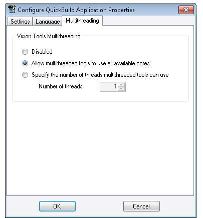
Cognex recommends you enable multithreading for conversion operations. In QuickBuild, choose Configure->QuickBuild Application Propertiesand enable multithreading as shown:
The CogCADToRange supports two Execute methods: