This topic contains the following sections.
The Height Calculator edit control provides a graphical user interface to the most commonly used features of the Cog3DRangeImageHeightCalculatorTool. The Range Image Height Calculator Tool provides height measurement capabilities for range images created by a Cognex 3D displacement sensor. The Height Calculator Tool measures the height of the "surface" defined by the range image pixels relative to a base plane defined by the user. The tool needs the following inputs:
- An InputImage (type CogImage16Range)
- A Region (type ICogRegion)
- A BasePlane (type Cog3DPlane)
- The calculated height statistics.
- Diagnostics data about how the range image pixels were used to calculate the height.
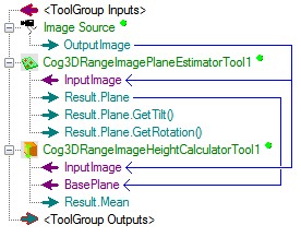
The Height Calculator Tool allows you to use a range image and measure the height of any feature of the object on it relative to the point on a plane that you defined as the base plane. The typical method of supplying a base plane is to use the Range Image Plane Estimator Tool.

The following table describes the function of each button:
| Button | Description | Function |
 | Run | Uses the specified Region and BasePlane to analyze the image stored in the Current.InputImage buffer to calculate the height. |
 | Electric mode | Toggles electric mode, where the Range Image Height Calculator tool executes automatically when particular configuration parameters change. In electric mode, a lightning bolt appears next to every electric property. |
 | Local image display | Opens or closes the local image display window. A Range Image Height Calculator tool supports the following image buffers:
|
 | Floating image display | Opens one or more floating image windows, which support the same image buffers as the local image display window. The floating display's toolbar shows the absolute height value of the range image pixels regardless of the base plane. |
 | Open | Opens a VisionPro persistence (.vpp) file that contains a set of saved properties for this vision tool object type. VisionPro reports an error if you try to open a .vpp file for another object type. |
 | Save | Saves the current properties of the vision tool to a VisionPro persistence (.vpp) file. The edit control allows you to choose between saving the vision tool with or without its image buffers and tool results. |
 | Save As | Saves the current properties of the vision tool to a new VisionPro persistence (.vpp) file. |
 | Reset | Resets the vision tool to its default state. |
 | Floating Results Display | Opens a new, separate results window, allowing you to view run results without turning to the Results tab. |
 | Show ToolTips | Enables or disables the display of tooltips for individual items in the edit control. |
 | Help | Opens this VisionPro online help file. |
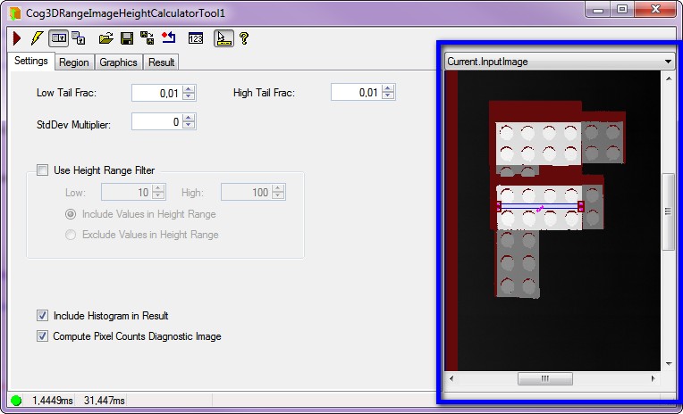
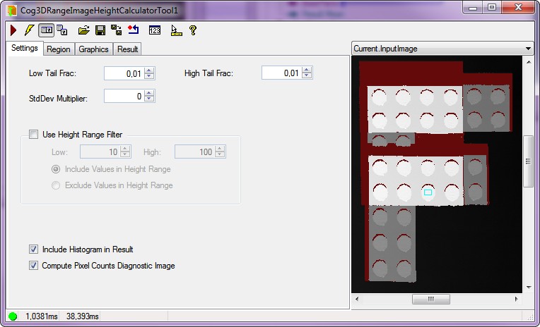
The local Image Display shows the input image, the height measurement region and - if defined - the mask to be applied. There are three kinds of images that you can display in this area:
- The Current.InputImage provides the input image to the Height Calculator tool. This is the InputImage buffer.
- The LastRun.InputImage displays the image that the tool last analyzed.
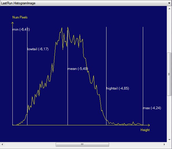
- The LastRun.Histogram buffer displays a histogram within the region of interest of the last image that the tool ran on.
Use the Settings tab to configure the Low and High Tail Fraction, whether you need Height Range Filtering and Histogram data. The following figure shows the default Settings tab:

| Feature | Description |
| Low Tail Frac (LowTailFrac) | The fraction which dictates how many of the lowest pixels are discarded before calculating the LowTail height. The default value is 0.01. The value must be between [0, 1]. The low tail height is the height at which the number of used pixels less than this height / total number of pixels used in the height calculation = LowTailFrac For example if the LowTailFrac is set to 0.01 then LowTail is set such that 1 percent of "used" pixel heights are below it. In some applications this value may be used to provide a more robust estimation of the real minimum height. This value is less sensitive to outlying or noisy height data. |
| High Tail Frac (HighTailFrac) | The fraction which dictates how many of the highest pixels are discarded before calculating the HighTail height. The default value is 0.01. The value must be between [0, 1]. The number of used pixels greater than this height / total number of pixels used in the height calculation) = HighTailFrac For example if the HighTailFrac is set to 0.01 then HighTail is set such that 1 percent of "used" pixel heights are above it. In some applications this value may be used to provide a more robust estimation of the real maximum height. This value is less sensitive to outlying or noisy height data. |
StdDev Multiplier (StdDevMult) | Standard deviation multiplier. Default value is 0 and can be either positive or negative. It is taken into account in the MeanPlusStdDevMult property: MeanPlusStdDevMult = Mean + standard deviation of all used pixel heights * StdDevMult The Mean Plus Standard Deviation Multiplier provides another method of making statistical observations about range image data, similarly to the Low and High Tail Fraction methods. |
| Use Height Range Filter (HeightRangeFilterEnabled) | Enables or disables the height range filter. The height range filter allows the user to exclude pixels which do not fall within a user selected range of height values. Enable the height range filter to help remove the effect of noisy or outlying height pixel data from the height calculation. The configured height range can be inverted by setting. When a height range filter is enabled, the endpoints of the height range filter (HeightRangeFilterLow, HeightRangeFilterHigh) are always included in the pixel values used to calculate the height. |
| HeightRangeFilterLow | The smallest height value to be included or excluded by the height range filter. The default value is 10. |
| HeightRangeFilterHigh | The largest height value to be included or excluded by the height range filter. The default value is 100. |
| Include Values in Height Range | HeightRangeFilterMode controls whether the height range filter includes or excludes the values between HeightRangeFilterLow and HeightRangeFilterHigh. The default value is: IncludeValuesInRange. |
| Exclude Values in Height Range | HeightRangeFilterMode controls whether the height range filter includes or excludes the values between the HeightRangeFilterLow and the HeightRangeFilterHigh. |
| Include Histogram in Result | IncludeHistogramInResult specifies whether or not to include the histogram data in the result. The default value is True. See Figure 1 below. |
| Compute Pixel Counts Diagnostic Image | ComputePixelCountsDiagImage specifies whether or not to include a pixel counts diagnostics image in the result. The pixel counts diagnostics image indicates which pixels in the range image were used by the height calculation. The default value is True. |
| Feature | Description |
| Region Mode | RegionMode controls how the optional run time region is applied to the input image. Controls whether the optional run time region (mask) is applied to the input image. |
| Plane Side | Specifies which side of the plane to consider the positive height direction when computing the height. The default value is: IncreasingPlaneNormal For more information, see Specifying which side of the plane is above the plane in the Calculating the Height of Features in 3D Images topic. |
| Region Shape |
Set the parameters for the Region based on which the Height Calculator tool will perform height measuring.
Adjust the various properties of the Region with the shape you selected. |
| Selected Space Name | The selected space name determines where the 2D region is placed when selecting the pixels will be used to calculate the height: |
| Select Mode | You can define the coordinates and size of your selected region shape. It may be easier to first specify the projection region graphically in the Current.InputImage buffer, then use these controls to fine tune the projection region parameters. The edit control updates the projection region values so that the values on this tab always match the shape of the projection region in the InputImage buffer. |
| Fit in Image | FitToImage centers the search region within InputImage. |
| Feature | Description |
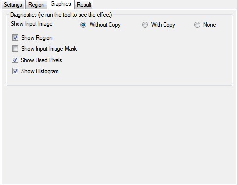
| Show Input Image |
Lets you choose the way the input image is displayed in the QuickBuild Job Editor's CogRecordsDisplay container (LastRunRecord):
|
| Show Region | Region includes the specified region in the QuickBuild Job Editor's CogRecordsDisplay container (LastRunRecord). |
| Show Input Image Mask | InputImageMask includes a graphic representing the input image mask in the QuickBuild Job Editor's CogRecordsDisplay container (LastRunRecord). |
| Show Used Pixels | UsedPixels includes a mask graphic representing which range image pixels were used in the height calculation in the QuickBuild Job Editor's CogRecordsDisplay container (LastRunRecord). |
| Show Histogram | SfIncludeHistogramInResult displays the Histogram in the QuickBuild Job Editor's CogRecordsDisplay container (LastRunRecord). |
| Feature | Description |
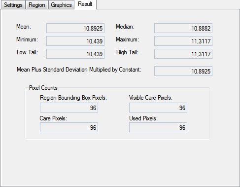
| Results |
|
| PixelCounts | Result information which identifies the number of pixels in the range image that fall into each of 4 different categories: |