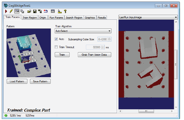
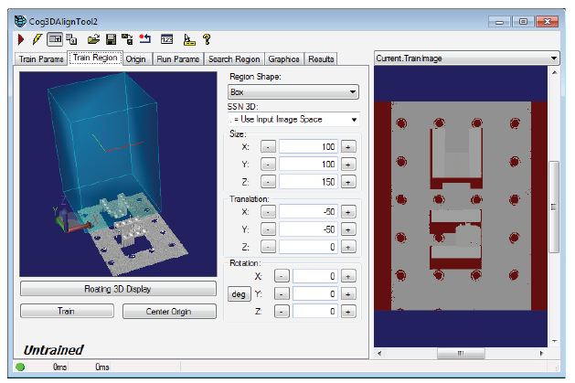
The 3D Align tool edit control provides a graphical user interface to the Cog3DAlignTool tool, which you use to define a 3D model, the volume of a 3D range image where you want to search for that 3D model, and other run parameters that define how your 3D models might be rotated about the X, Y and Z axes in successive runtime images. The following figure shows the 3D Align tool edit control with a trained pattern and defined search region:
The tool returns a Cog3DAlignResults object containing a collection of results for each instance of the 3D model found in the runtime image.
The edit control supports the following features:
The following table describes the function of each button:
| Button | Description | Function |
 | Run | Search the Current.InputImage for the trained 3D model. |
 | Electric mode | Toggle electric mode, where the 3D Align tool executes automatically when particular configuration parameters change. In electric mode, a lightning bolt appears next to every electric property. |
 | Local image display | Open or close the local image 2D display window. A 3D Align tool supports the following image buffers:
|
 | Floating image display | Open one or more floating image 2D display windows, which support the same image buffers as the local image display window. |
 | Open | Open a VisionPro persistence (.vpp) file that contains a set of saved properties for a 3D Align tool. VisionPro reports an error if you try to open a .vpp file for another type of vision tool. |
 | Save | Save the current properties of the vision tool to a VisionPro persistence (.vpp) file. The edit control allows you to choose between saving the vision tool with or without its image buffers and tool results. |
 | Save As | Save the current properties of the vision tool to a new VisionPro persistence (.vpp) file. |
 | Reset | Reset the vision tool to its default state. The tool gives you a choice between resetting to the default-constructed state, which is appropriate when you are using it in a Visual Studio.NET application, or its template-initialized state, which is appropriate for QuickBuild applications. |
 | Show Floating Results | Open a separate results window with the same contents as seen in the Results tab. |
 | Show ToolTips | Enable or disable the display of tooltips for individual items in the edit control. |
 | Help | Open this VisionPro software documentation. |
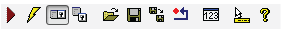
Use the Train Params tab to set parameters related to creating a trained 3D model:
The tab supports the following parameters:
| Parameter | Description |
| Pattern window | The Train Params tab supports an embedded 3D Viewer showing the trained 3D model if one exists:
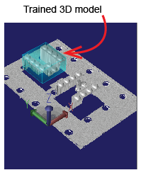 |
Train Algorithm | The 3D Align tool supports three alignment algorithms for training a 3D model:
You should verify that the chosen algorithm provides the speed, accuracy, and robustness that you need for your application. If it does not, you can explicitly try the other algorithm. |
Subsampling Cube Size | Specify the length of one side of a cube in 3D space that tool uses to subsample the input vision data at a coarse resolution to quickly identify candidate areas that might match the pattern. The value allows you to control the tradeoff between alignment speed (higher values) and accuracy (lower values). Cognex recommends the default value for a wide variety of patterns. Enable the Auto checkbox to automatically select a cube size that represents a good tradeoff between runtime speed and accuracy. Disable the checkbox if your application requires higher accuracy or smaller execution times than the default value generates. |
| Train Timeout (TrainTimeout) | Set a maximum execution time (in milliseconds) for the tool to train a 3D model from the current pattern. The default value is 6 seconds. |
Creates a trained 3D model from the current pattern data. If a trained pattern already exists it is untrained and then retrained. The tool creates a trained 3D model from the current train region. Use the Train Region tab to specify the region of the pattern you want to train before clicking the Train button. | |
| Grab Train Vision Data | Change the TrainVisionData property to reference the InputVisionData property in order to select the 3D data that will be used to create a 3D model. Use a 3D range image that contains sufficient detail about the object(s) you want to locate in run-time images. |
Use the Train Region tab to select which portion of the Current.TrainImage buffer will be used to create a 3D pattern. You must click Grab Train Vision Data on the Train Params tab and fill the Current.TrainImage buffer before you can create a train region. By default the tool uses a Cog3DBox centered at (0, 0, 75) with a size of (100, 100, 150) and no rotation:
The tab supports an embedded 3D Viewer for viewing the train region as well as the following parameters:
| Parameter | Description |
| Region Shape (TrainRegion) | By default the tool uses a Cog3DBox as a region shape. Depending on the 3D data you are using you can switch to using the entire Current.TrainImage buffer to create a trained 3D model pattern. |
| SSN 3D (SelectedSpaceName3D) | The 3D coordinate space in which the Cog3DBox is to be interpreted. |
Size, Translation, and Rotation controls. | Use the Size, Translation, and Rotation controls to resize and position the Cog3DBox train region.
The edit control allows you to type numeric values into the appropriate number box or by clicking the corresponding increment (+) or decrement (-) buttons. Click and hold one of these buttons to change the value continuously. Be aware of the unique behaviors of the controls due to the unusual characteristics of 3D-pose representation:
Click Floating 3D Display to open a floating 3D Viewer, which you can interact with to make it easier to see how the changes you make to the Size, Translation, and Rotation controls affect the Cog3DBox train region. Resize and reposition the train region until it encompasses the portion of the pattern you want to train as a 3D model: 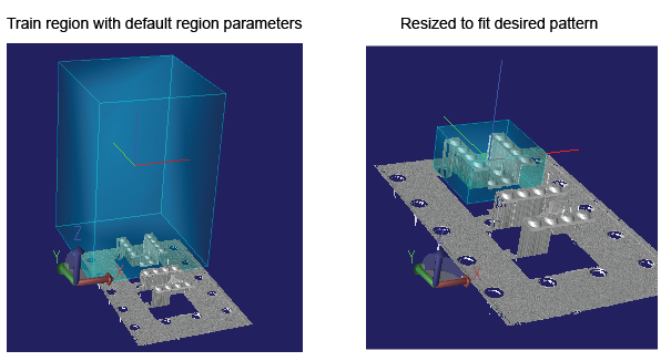 Note: Do not intersect the train region with the base plane whenever possible. A 3D model that includes features from the base plane will have a negative impact on the performance of the 3D Align tool. |
| Train | Creates a trained 3D model from the current pattern data. If a trained pattern already exists it is untrained and then retrained. |
| Center Origin | Position the origin at the center of the current train region. |
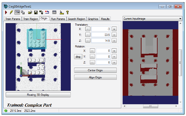
Use the Origin tab to specify the location of the 3D pattern origin with respect to the trained pattern.
| Parameter | Description |
Translation, and Rotation controls. | Use the Translation, and Rotation controls to position the origin relative to the trained pattern.
The edit control allows you to type numeric values into the appropriate number box or by clicking the corresponding increment (+) or decrement (-) buttons. Click and hold one of these buttons to change the value continuously. Click Floating 3D Display to open a floating 3D Viewer, which you can interact with to make it easier to see how the changes you make to the controls affect the origin. |
| Center Origin | Position the origin at the center of the current train region. |
| Align Origin | Adjust the origin rotation to match that of the train region. |
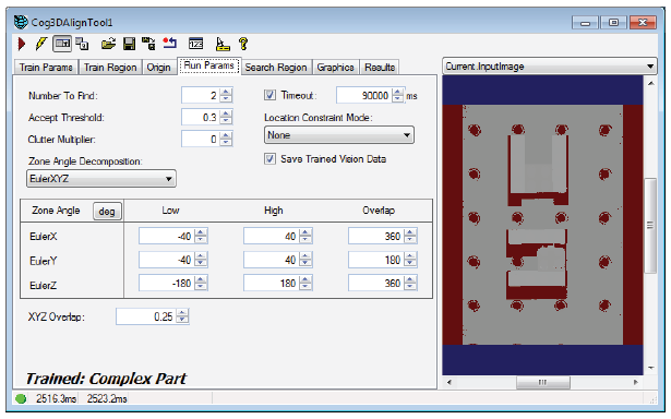
Use the Run Params tab to provide the 3D Align tool with the run parameters necessary to locate the trained 3D pattern in successive runtime images, including the three angle zones for the 3D coordinate system.
| Parameter | Description |
| Number To Find | Set this value to the maximum number of pattern instances that you expect to find in your input image. The number of results returned will always be less than or equal to the value you specify. |
| Accept Threshold (AcceptThreshold) | Only instances of the pattern that receive scores greater than or equal to this threshold are reported as results. Supply an acceptance threshold that is lower than the lowest score you ever expect to receive from a true instance of your pattern. |
Clutter Multiplier | This value controls how much the score of your result will be reduced by the presence of extraneous data points (clutter) at the result location. They appear in the runtime image at locations that should be empty. A runtime data point is considered clutter if it lies within the bounding box of the found pattern (as returned by GetBoundingBox), but does not match any point on that pattern. |
| Timeout | Set the maximum execution time for this 3D Align tool. |
Location Constraint Mode | Filter whether candidate results are valid by choosing one of the following constraints:
By default, the 3D Align tool does not constrain results. |
| Save Trained Vision Data (SaveTrainedVisionDataInResults) | Save a reference to the trained vision data in the results object. This is required to display the trained model graphics on the edit control results tab |
Zone Angle Decomposition | The 3D Align tool supports two ways of interpreting the three angle zones you use to specify how the rotation of the 3D pattern can appear in any runtime image:
The Zone Angle section of the edit control will reflect your choice for zone angle decomposition: 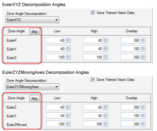 |
Zone Angle zones
| A single rotation about an arbritray axis in 3D space can be described by three angles known as Euler angles , which decompose the single rotation (about the abritrary axis) into a sequence of rotations about three known coordinate system axes. Applying these three rotations in sequence is equivalent to the single rotation about the arbritray axis. Specify the allowed range of 3D rotations using three Euler angle zones. Each zone describes a range of rotations about a known coordinate system axis. If you choose the EulerXYZ decomposition mode:
If you choose the EulerZYZMovingAxes decomposition mode:
Set a High and Low value for this angle zone. In addition, set a Overlap value. Two result candidates are said to overlap in this angle zone if the absolute difference between their angles is less than or equal to this Overlap threshold. When two pattern instances overlap in volume, and also overlap in all three angle zones, the operator discards the pattern match with the lower score. |
XYZ Overlap | Two result candidates overlap in volume if the fraction of their volume that overlaps is greater than this value. When two pattern instances overlap in volume, and also overlap in all three angle zones, the 3D Align tool discards the pattern instance with the lower score. |
Use the Search Region tab to define the area of each runtime image where the 3D Align tool searches for the trained pattern.
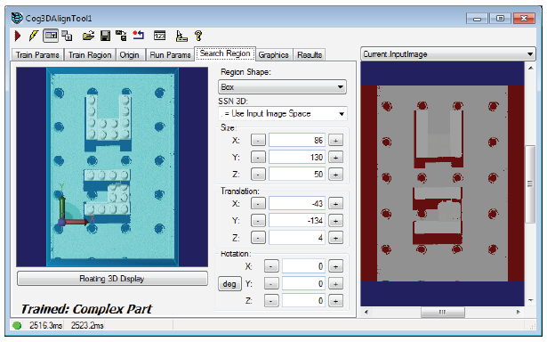
The tab supports the following parameters:
| Parameter | Description |
| Region Shape (TrainRegion) | By default the tool searches the entire 3D range image, but you can choose to limit the search region to a Cog3DBox. |
| SSN 3D (SelectedSpaceName3D) | The 3D coordinate space in which the Cog3DBox is to be interpreted. |
Size, Translation, and Rotation controls. | Use the Size, Translation, and Rotation controls to resize and position the Cog3DBox search region.
The edit control allows you to type numeric values into the appropriate number box or by clicking the corresponding increment (+) or decrement (-) buttons. Click and hold one of these buttons to change the value continuously. Be aware of the unique behaviors of the controls due to the unusual characteristics of 3D-pose representation:
Click Floating 3D Display to open a floating 3D Viewer, which you can interact with to make it easier to see how the changes you make to the Size, Translation, and Rotation controls affect the Cog3DBox search region. Resize and reposition the search region until it encompasses the portion of the pattern you want to search for the trained 3D pattern: 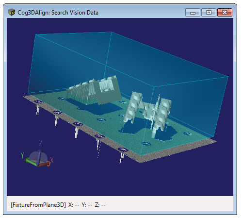 |
The Graphics tab provides access to a subset of the CurrentRecordEnable, LastRunRecordEnable, and LastRunRecordDiagEnable graphics flags.
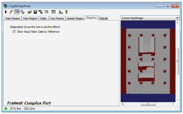
By default, the 3D Align tool includes a reference to the 3D input data in the LastRunRecord. The last run record is obtained by calling the CreateLastRunRecord method.
The Results tab displays the contents of the Cog3DAlignResults collection generated by running the 3D Align tool:
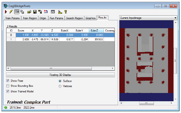
The tab displays the following results for each found instance of the 3D model:
| Result | Description |
| Score | Higher values indicate a better match between the trained pattern and the runtime image. The results in the collection are sorted in order of decreasing score. |
| X, Y, Z (Translation) | The location of the origin for this found pattern as measured in the selected 3D space of the Current.InputImage. |
EulerX, EulerY, and EulerZ | The rotation for this Cog3DTransformRotation result. A 3D rotation can be decomposed by either a Cog3DEulerXYZ or Cog3DEulerXYZMovingAxes structure. Choose which structure you use for this 3D Align tool on the Run Params tab, but be aware the tab always displays the rotation in terms of Cog3DEulerXYZ. |
| Coverage | The coverage value represents the fraction of points from the trained pattern that were found in the runtime image. |
| Clutter | The clutter value of each result measures the relative number of extraneous data points that were found in the runtime image. |
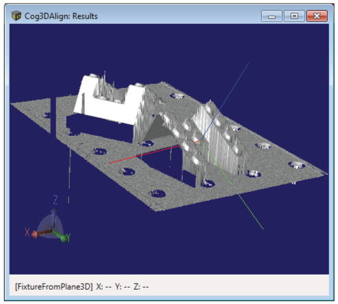
Click Floating 3D Display to open a floating 3D Viewer to view the results graphically, with the X-axis in red, the Y-axis in green and the Z-axis in blue. The Results tab supports the following options:
Show Pose: Display the pose of the selected result as a graphical set of coordinate axes that reflect the found position and orientation:
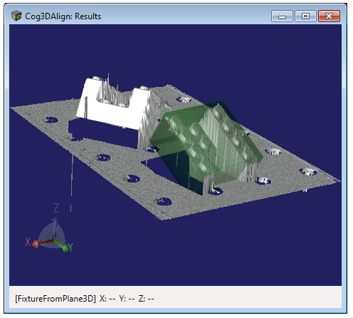
Show Bounding Box: Display the bounding box surrounding the pose at its found position and orientation as a translucent dark green box:
Show Trained Model: Display the actual trained model points rendered at their found position and orientation as a bright green set of points:
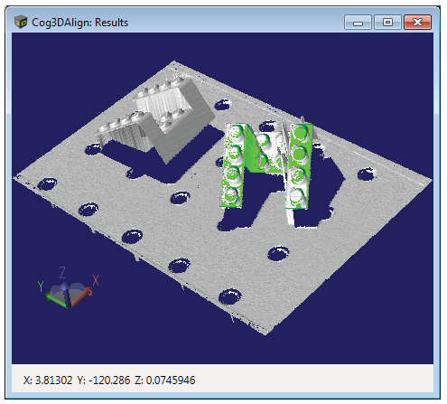
Be aware that this option requires that the Save Trained Vision Data checkbox on the Run Params tab be enabled when the tool executed.
- Toggle between Surface and Vertices modes to switch how the floating display presents the result data. Viewing the results in Vertices mode can be desirable when viewing the trained model points.
Note: Vertices mode is not available when using a Cognex Vision Controller.