Input and Output Timing
You can configure the timing characteristics of the input and output lines on the Communications tab of the Settings menu and in the Finalize step of training. For more information, see Communications and Set Trigger Mode.
You can customize the amount of delay the vision sensor applies to trigger and output signals to facilitate integrating it into your production line.
-
The Trigger Delay setting monitors the trigger signal and postpones image acquisition until the trigger delay period expires. You can set the Trigger Delay time between 0 ms (default) and 1000 ms. If set to 0, acquisition starts immediately. The Trigger Delay is included in the reported cycle time. You can only set the Trigger Delay when the vision sensor is in Single trigger mode.
Note: The vision sensor cannot process incoming triggers if they arrive during the delay period of a previous trigger, or while image acquisition is ongoing from a previous trigger. Such an event results in a trigger error. -
Trigger-to-Output Delay is the time delay between when the vision sensor receives a trigger and when it sends the output to device IO, TCP, or industrial protocols. The vision sensor queues outgoing inspection results, and outputs them in the order of inspection. You can set the delay between 0 (default) to 2000 ms.
Note:-
If the Trigger-to-Output Delay is 0 or smaller than the cycle time (that is, the delay elapses before the inspection is completed), the vision sensor sends the output immediately after the inspection.
-
If you change the delay, all queued inspection results are cleared.
-
The Trigger-to-Output Delay does not apply to SFTP output or web events.
-
-
DIO Pulse Length is the pulse length of the discrete IO. You can set the pulse length between 5 (default) and 1000 ms.
During normal operation, the vision sensor conducts image inspection and can also indicate trigger errors. However, incorrect settings can lead to inaccurate or contradictory results. The following examples illustrate how the different input and output settings interact with each other.
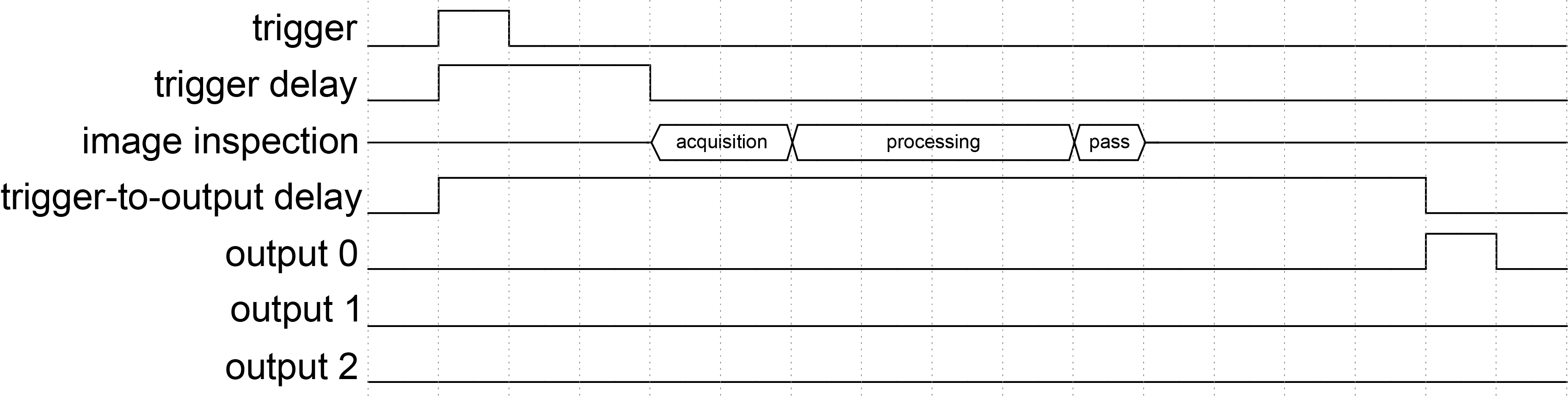
Normal Inspection Cycle
This example assumes the following discrete I/O configuration:
| Trigger | Trigger Delay | Trigger-to-Output Delay | Discrete I/O Pulse Length |
| Single | 30 ms | 140 ms | 10 ms |
-
The vision sensor receives a trigger.
-
The vision sensor waits until the 30 ms trigger delay period expires.
-
The vision sensor acquires and then processes the image. The result is a pass.
-
The vision sensor waits until the 140 ms trigger-to-output delay period expires.
-
The vision sensor pulses output line 0 for 10 ms, which signals the pass result.
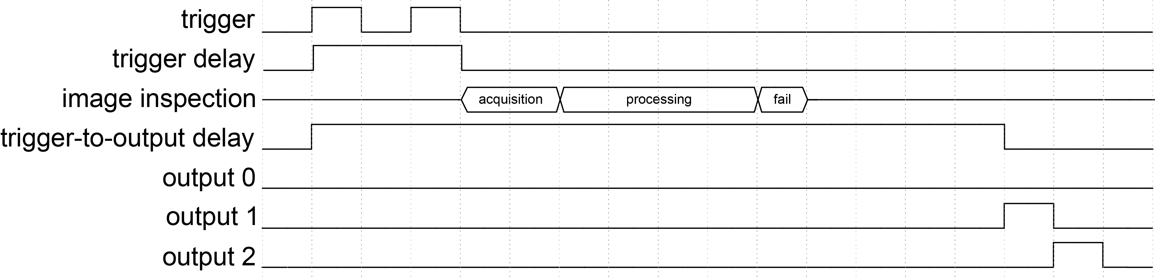
Trigger Errors
The vision sensor cannot process triggers that arrive during the delay period of a previous trigger or during image acquisition initiated by a previous trigger. When this occurs, the vision sensor indicates a trigger error by pulsing output line 2.
This examples assumes the following discrete I/O configuration:
| Trigger | Trigger Delay | Trigger-to-Output Delay | Discrete I/O Pulse Length |
| Single | 30 ms | 140 ms | 10 ms |
-
The vision sensor receives the first trigger.
-
The vision sensor waits until the 30 ms trigger delay period expires.
-
During the trigger delay, the vision sensor receives a second trigger.
-
The vision sensor rejects the second trigger because the trigger delay period of the first trigger is still ongoing.
-
-
When the trigger delay period of the first trigger expires, the vision sensor acquires the image and process the image. The result is a fail.
-
The vision sensor waits until the 140 ms trigger-to-output delay period expires.
-
The vision sensor pulses output line 1 for 10 ms. This signals the fail result for the image acquisition triggered by the first trigger.
-
The vision sensor pulses output line 2 to signal that a trigger error occurred caused by the second trigger.
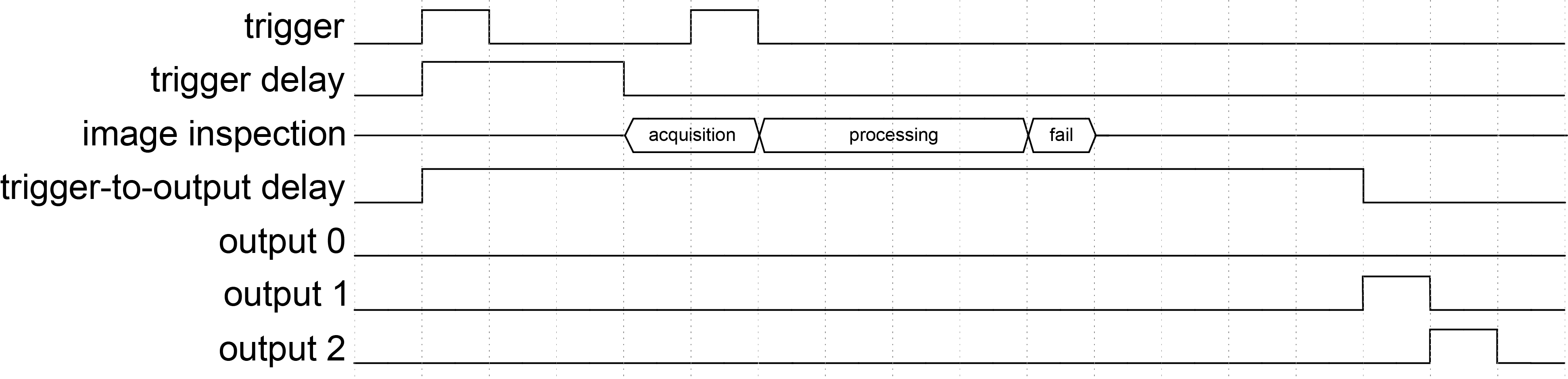
This examples assumes the following discrete I/O configuration:
| Trigger | Trigger Delay | Trigger-to-Output Delay | Discrete I/O Pulse Length |
| Single | 30 ms | 140 ms | 10 ms |
-
The vision sensor receives the first trigger.
-
The vision sensor waits until the 30 ms trigger delay period expires.
-
The vision sensor acquires the image.
-
During image acquisition, the vision sensor receives a second trigger.
-
The vision sensor rejects the second trigger and continues processing the image acquired with the first trigger. The result is a fail.
-
-
The vision sensor waits until the 140 ms trigger-to-output delay period expires.
-
The vision sensor pulses output line 1 for 10 ms. This signals the fail result for the image acquisition triggered by the first trigger.
-
The vision sensor pulses output line 2 to signal that a trigger error occurred caused by the second trigger.
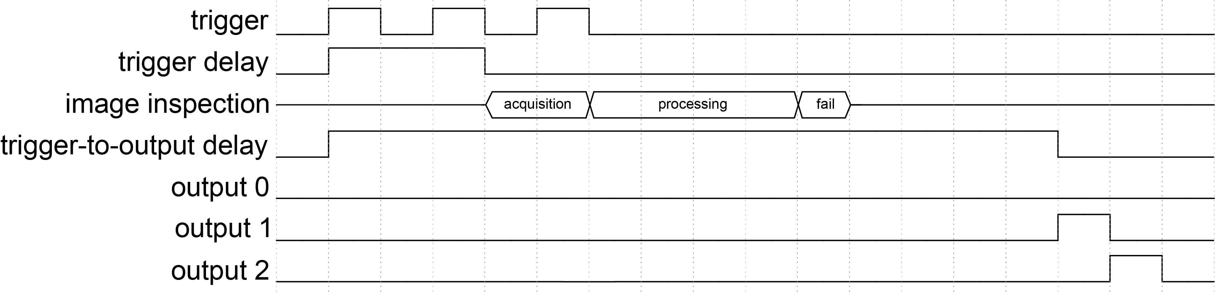
This examples assumes the following discrete I/O configuration:
| Trigger | Trigger Delay | Trigger-to-Output Delay | Discrete I/O Pulse Length |
| Single | 30 ms | 140 ms | 10 ms |
-
The vision sensor receives the first trigger.
-
The vision sensor waits until the 30 ms trigger delay period expires.
-
During the trigger delay, the vision sensor receives a second trigger.
-
The vision sensor rejects the second trigger because the trigger delay period of the first trigger is still ongoing.
-
-
The vision sensor acquires the image.
-
During image acquisition, the vision sensor receives a third trigger.
-
The vision sensor rejects the third trigger and continues processing the image acquired with the first trigger. The result is a fail.
-
-
The vision sensor waits until the 140 ms trigger-to-output delay period expires.
-
The vision sensor pulses output line 1 for 10 ms. This signals the fail result for the image acquisition triggered by the first trigger.
-
The vision sensor pulses output line 2 to signal that a trigger error occurred caused by the second and the third trigger.
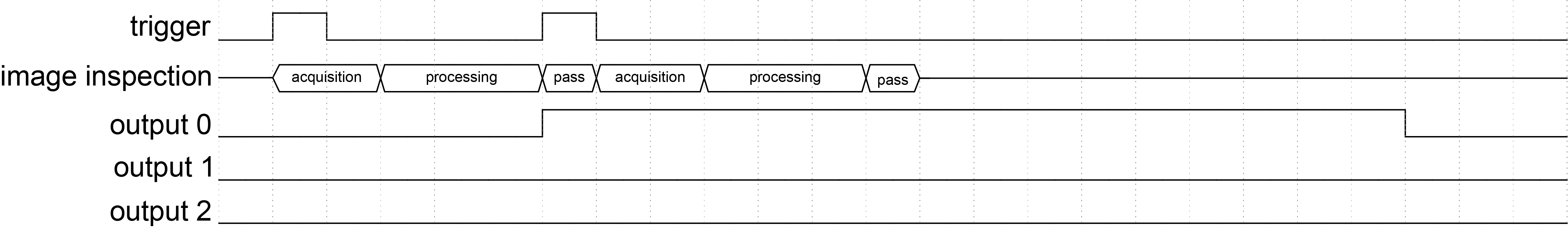
Incorrect or Contradictory Result Signals
The vision sensor outputs incorrect or contradictory result signals if the output pulse length is longer than the interval between parts. This results in the output pulses overlapping:
-
Two sequential inspections with the same result appear as one continuous pulse.
-
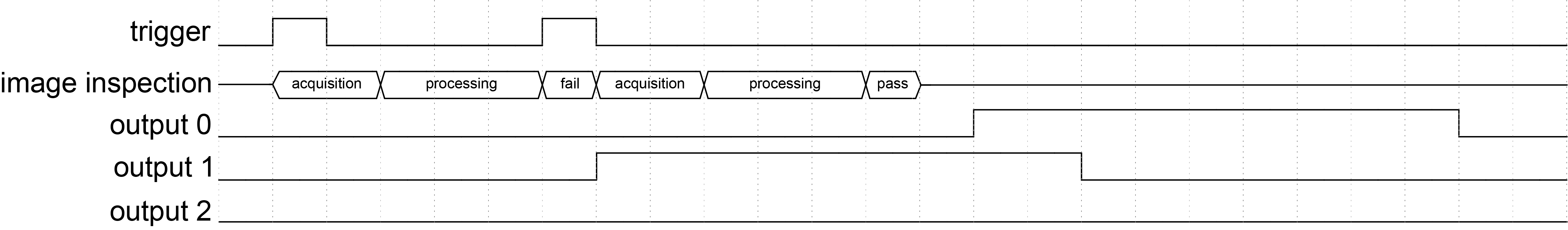
Two different, sequential inspection results cause both lines to be high at the same time.
This example assumes the following discrete I/O configuration:
| Trigger | Trigger Delay | Trigger-to-Output Delay | Discrete I/O Pulse Length |
| Single | 0 ms | 0 ms | 100 ms |
-
The vision sensor receives the first trigger, then immediately starts to acquire and process the image.
-
During the evaluation of the first inspection, the vision sensor receives a second trigger.
-
The vision sensor queues the second image acquisition until the first image is evaluated as a pass.
-
The vision sensor pulses output line 0, which signals the pass result.
-
The vision sensor acquires, processes, and evaluates the second image, then outputs the pass result.
-
Since the output pulse length is set to 100 ms, The two pass results merge and appear as one 160 ms pulse on output line 0.
This example assumes the following discrete I/O configuration:
| Trigger | Trigger Delay | Trigger-to-Output Delay | Discrete I/O Pulse Length |
| Single | 0 ms | 0 ms | 90 ms |
-
The vision sensor receives the first trigger, then immediately starts to acquire and process the image.
-
During evaluating the result of the first inspection, the vision sensor receives a second trigger.
-
The vision sensor queues the second image acquisition until the first image is evaluated as a fail.
-
The vision sensor pulses output line 1, which signals the fail result.
-
The vision sensor acquires, processes, and evaluates the second image, then outputs the pass result.
-
Since the output pulse length is set to be 90 ms, the two inspection results overlap, causing both output line 0 and 1 to be high for 20 ms.