This topic contains the following sections.
The Color Segmenter tool provides a graphical user interface to the CogColorSegmenterTool, which you use to separate pixels from a color image into a grey scale image of light and dark pixels, where light pixels represent color pixels that fall within a desirable range of color and dark pixels represent color pixels that fall outside any desirable range of color. The grey scale image that a Color Segmenter tool generates represents just the portion(s) of the input image having color values that you want to analyze further. The following figure shows the Color Segmenter tool edit control:

The edit control allows you to perform the following actions:
- Build a collection of color ranges, using a color space of either Red, Green, Blue (RGB) or Hue, Saturation, Intensity (HSI).
- Increase or decrease the allowed values for each color range.
- Establish a range of color values which the Color Segmenter tool will represent with varying shades of grey in the output image.
- Define the shape, size and location of the region the tool will use to examine the color contained in each acquired image.
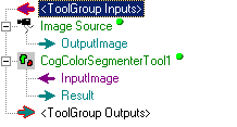
If you add a CogColorSegmenterTool to a QuickBuild Job, it appears with an input terminal for the incoming color image and an output terminal for the outgoing grey scale image it generates, as shown in the following figure:
See the topic Adding Edit Controls to Visual Studio for details on how to add a Color Segmenter edit control to your Visual Studio.NET development environment if you are creating a vision application using the VisionPro application programming interface (API). The QuickBuild development environment supports the Color Segmenter edit control automatically.

The following table describes the function of each button:
| Button | Description | Function |
 | Run | Generate the segmented image based on the current collection of color ranges. |
 | Local image display | Open or close the local image display window. A Color Segmenter tool supports the following image buffers:
|
 | Floating image display | Open one or more floating image windows, which support the same image buffers as the local image display window. |
 | Open | Open a VisionPro persistence (.vpp) file that contains a set of saved properties for this vision tool object type. VisionPro reports an error if you try to open a .vpp file for another object type. |
 | Save | Save the current properties of the Color Segmenter tool to a VisionPro persistence (.vpp) file. The edit control allows you to choose between saving the Color Segmenter tool with or without its image buffers and tool results. |
 | Save As | Save the current properties of the vision tool to a new VisionPro persistence (.vpp) file. |
 | Reset | Reset the vision tool to its default state. The tool gives you a choice between resetting to the default-constructed state, which is appropriate when you are using it in a Visual Studio.NET application, or its template-initialized state, which is appropriate for QuickBuild applications. |
 | Show ToolTips | Enable or disable the display of tooltips for individual items in the edit control. |
 | Help | Open this VisionPro online help file. |
Use the Colors tab to generate the collection of color ranges that the Color Segmenter tool will use to generate a segmented image. The following figure shows the Colors tab with a single defined color range:
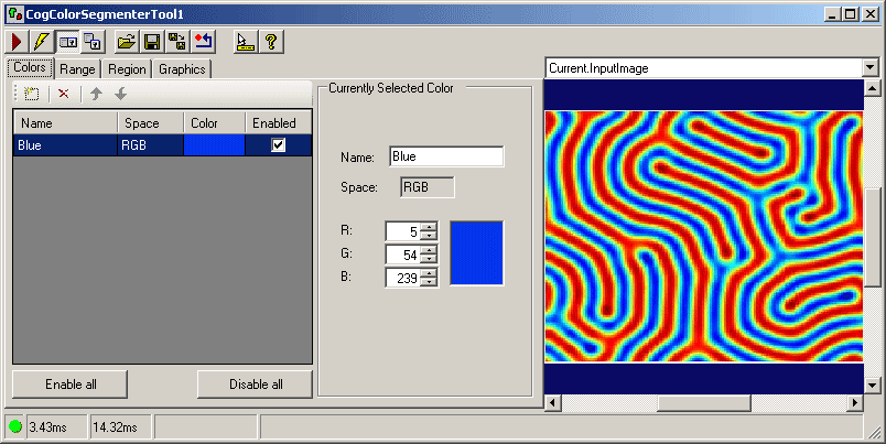
The Colors tab displays a grid of the ColorCollection currently defined for the Color Segmenter tool. Use the function buttons shown in the following figure to add, delete and reorder the items in the reference table:

The following table describes what each button does:
| Button | Description |
 | Add a new color range using either a specific point or by selecting a region of the Current.InputImage. If you use a point to specify the new color range, the Colors tab displays a point graphic over the Current.InputImage, as shown in the following figure: 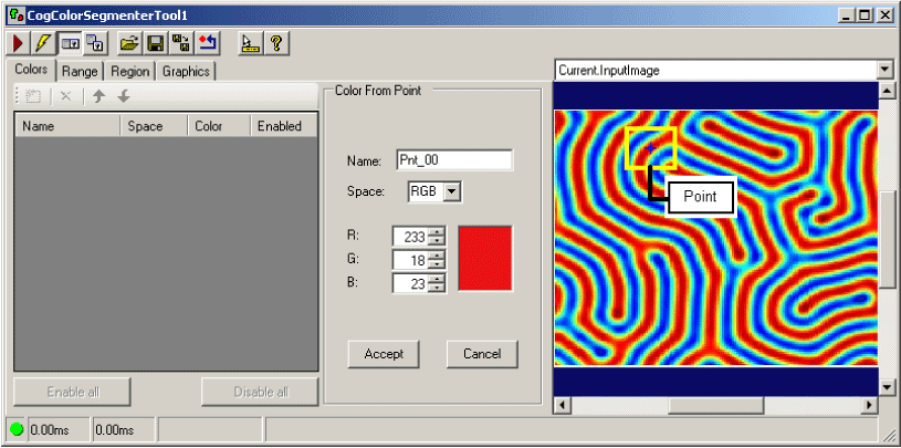 On the other hand, if you use a region to specify the new reference color, the Colors tab displays a region graphic over the Current.InputImage as well as the ability to control the properties of the region, as shown in the following figure: 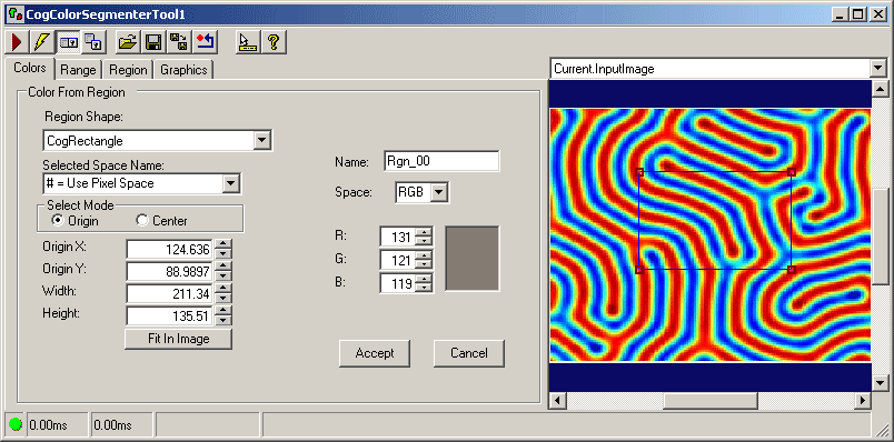 In either case, select a point or region to add to your color collection and click Accept. The following figure shows a Colors tab with a single color range:  |
 | Remove the selected color from the reference table. |
 | IndexOf the selected color up one position in the reference table, although the order of the reference colors does not affect the operation of the Color Segmenter tool. |
 | IndexOf the selected color down one position in the reference table, although the order of the reference colors does not affect the operation of the Color Segmenter tool. |
The Colors tab also includes an area for modifying the colors in the collection:

The following table describes these controls:
| Control | Description |
| Name | A name for the reference color that you can assign and change. |
The color space for the current image. The tab displays the current values for Plane0, Plane1, and Plane2 for images in the RGB color space, or the values for Plane0, Plane1 and Plane2 in the HSI color space. |
Use the Range tab to modify the current range along any one plane in the color space the image the currently uses. The Color Segmenter starts with a default range for each color plane, but you can use the graphics in the Range tab to increase or decrease the color values the tool will consider to be within the allowable range. The following figure shows a Range tab corresponding to a particular image:

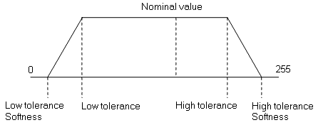
Any particular color range can be defined by the following parameters:
- The nominal value indicates the average color value in the particular color space (RGB or HSI) defined for the image.
- The low and high tolerance for any plane in the color space indicates the lower and upper values, respectively, that a pixel value can have in that color plane and be considered within the desired range.
The low and high tolerance softness values indicate pixels in the color plane for which the tool will apply a weighted value in the segmented image, ultimately giving the output pixel a grey value higher than 0 but less than 255.
These weighted pixels represent pixel values at either end of the desirable color range, and can be analyzed by another vision tool, such as a Blob tool, to collect such information as the area and center of mass of particular objects in the original color image.
Graphically, these parameters can be represented by the following figure:
The Range tab represents these parameters over a histogram of the values in the current plane, as shown in the following figure:
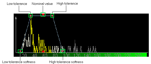
Use the handles in the graphic to select a particular parameter and slide it closer or farther away from the nominal value. Increasing the distance between the low and high tolerance values increases the range of pixels the Color Segmenter tool will consider for the output image. Increasing the low and high tolerance softness settings increases the amount of pixels in the output image that will have a grey value between 0 and 255.
The Range tab provides precise control over these parameters with the following settings::
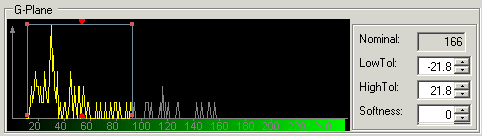
| Control | Description |
| Nominal | The nominal value for the selected color range. |
| LowTolerance | The low end of the allowable range of values for this color plane = Nominal + LowTol |
| HighTolerance | The high end of the allowable range of values for this color plane = Nominal + HighTol |
| Softness | The softness value at either end of the current range. The tool enforces a uniform software range at the low end and high end of the tolerance values. |
The Range tab also includes the following settings:
| Control | Description |
Select the particular color plane for which you want to specify an allowable range of pixel values. The tab displays the current values for PlaneRange0, PlaneRange1, and PlaneRange2 for images in the RGB color space, or the values for PlaneRange0, PlaneRange1 and PlaneRange2 in the HSI color space. | |
| Name | The name for this color range |
Histogram Graph | Specify whether you want to view the histogram for the current plane using a linear or logarithmic graph. Both options represent the same data, but the logarithmic plot expands the size of peaks that are small in a linear plot. This can be helpful for viewing histograms containing a small amount of data about the amount of color along any one plane in the image. |
Use the Region tab to specify the type of region you want to use to examine the run-time image. By default, the region of interest is configured to encompass the entire input image, but some applications might examine just a portion of each acquired image. For example, the following figure shows the Region tab configured to use a rectangular region of interest:

Use the following controls to determine the region of interest:
| Feature | Description |
Select the shape of the input region. Selecting "None=Use entire image" means that the tool uses the entire input image. A Color Segmenter tool supports the following input region shapes: The set of region-defining parameters that appear depend on the region shape you use. | |
| SelectedSpaceName | The coordinate space in which the region is interpreted. For more information, see Coordinate Space Names. |
| Select Mode | Available when Region Shape is CogRectangle or CogRectangleAffine. Selects the set of parameters that define the rectangle. If cogRectangleAffine is chosen, note that the angles of rotation and skew can be specified in degrees or radians, although the underlying tool keeps the measurements in radians. |
| FitToImage | Centers the copy region within Current.InputImage. |
Use the Graphics tab to specify the type of graphics the tool should use to indicate various results in the LastRun.InputImage and LastRun.SegmentImage image buffers. The following figure shows the Graphics tab:

Use the following settings to enable or disable particular graphics:
| Option | Description |
Enable an overlay color in the LastRun.InputImage representing those pixels from the Current.InputImage that the tool considers to be within a desirable color range. Click Overlay Color to choose a color other than the default green. | |
| Show Segmented Image | Generate the LastRun.SegmentImage which contains the grey scale image of light and dark pixels, where the light pixels represent those color pixels from the Current.InputImage that the tool considers to be within a desirable color range. |
| Option | Description |
| Show Input Image | Determine whether or not the input image is recorded as part of the diagnostic record, and whether the image is copied to the record or saved in the record as a reference. |
| Show Region | Enable a graphic representing the input region for the LastRun.InputImage. |