This topic contains the following sections.
Your QuickBuild application can use the discrete input and output capabilities of a Cognex frame grabber or Measurement Computing board to communicate with the external equipment of your production environment. QuickBuild can accept the discrete input signals necessary to control the application from remote sources, as well as generate the discrete output signals necessary to transmit tool results and other result data to the devices necessary to complete the overall vision task.
See the topic Using I/O Lines for more information on how VisionPro maps input and output lines to the physical connections on various Cognex frame grabbers. When you are ready to configure discrete I/O for a QuickBuild application, use the Communications Explorer as described in the topic Using the Communications Explorer.
This topic provides the background information about the discrete I/O signals that QuickBuild supports.
QuickBuild uses the definitions contained in the file VisionPro.ini to define the I/O hardware you use to communicate with external equipment. To successfully receive and send discrete I/O signals through your Cognex frame grabber or Measurement Computing board, the settings in VisionPro.ini must match the I/O hardware you plan to use.
The VisionPro.ini file contains default settings which might or might not match the I/O hardware you have installed. For example, if you use a Cognex MVS-8504 frame grabber, the default setting in VisionPro.ini defines a reference to the external opto-isolated I/O module 800-5712-3 as shown:
;******************************************************************************
; This section specifies the configuration of 8504 frame
; grabbers.  Additional sections should be added if there are more
; than two 8504 boards installed.  The possible settings are:
;
;     IOConfig = Standard     : Pass-through TTL connection module
;                               800-5818-1 with cable 300-0390
;     IOConfig = External     : External opto-isolated I/O module
;                               800-5712-3 with cable 300-0389
;     IOConfig = Split        : External opto-isolated I/O module
;                               800-5712-3 and TTL terminal block
;                               with cable 300-0399
;
[CogFrameGrabber8504 #0]
IOConfig = External
If you plan to use the pass-through TTL connection module 800-5818-1 with your Cognex 8504, you must edit this reference to IOConfig, as shown:
[CogFrameGrabber8504 #0]
IOConfig = Standard
See the topic Configuring VisionPro.ini for information on modifying the file, which by default is located in the Windows folder.
As a QuickBuild application executes it accepts image acquisition triggers and uses the vision tools it contains to analyze each image and generate results. While analyzing each acquired image, the ability of the application to respond to input signals and generate output signals depends on whether QuickBuild I/O functions are Online or Offline.
While Online, a QuickBuild application can interact with external equipment configured to send outgoing signals or accept incoming data. QuickBuild supports a variety of discrete input signals that perform an assortment of tasks including the ability to run all the Jobs within the application once or continuously, perform an emergency stop of all Jobs, or even toggle the current Online/Offline status of the application. The discrete output signals that a QuickBuild application can generate include tool results, the signal that an image acquisition has completed, or a pulsed signal that simply indicates that the application is currently Online. See the section Signal Types for a list of all valid incoming and outgoing signals a QuickBuild application can use. Deployed QuickBuild applications typically operate Online.
While Offline, a QuickBuild application cannot generate any output signals and disregards incoming signals that would control the application, with two exceptions:
- The input signal that switches QuickBuild to Online
- The signal that forces all Jobs within the application to stop executing
An application that is currently Offline can still run the Jobs it contains, but it cannot be switched Online while any Job is running. In addition, the state of output signals cannot be defined while an application is Offline, and are likely to exist in whatever state they were in when the application switched from Online to Offline. You typically use QuickBuild in an Offline status as you develop your application and run your Jobs without interacting with external devices.
There are several ways to switch the status of your application between Online and Offline:
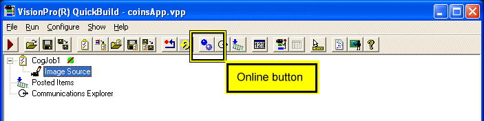
Click the Online button on the QuickBuild button bar:
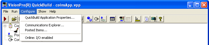
Choose Configure: Online I/O enabled from the QuickBuild Configuration menu.
Send your application an Online input signal.
See the section Signal Types for a list of all input signals a QuickBuild application can receive.
The QuickBuild button bar and status bar will indicate when QuickBuild is Online. Finally, be aware that the QuickBuild application can still respond to incoming acquisition triggers, activate connected strobe lights, and run the Jobs it contains regardless of whether the application is Online or Offline.
Your QuickBuild application can accept and generate a variety of discrete I/O signals and communicate with external equipment attached to your Cognex frame grabber or Measurement Computing board.
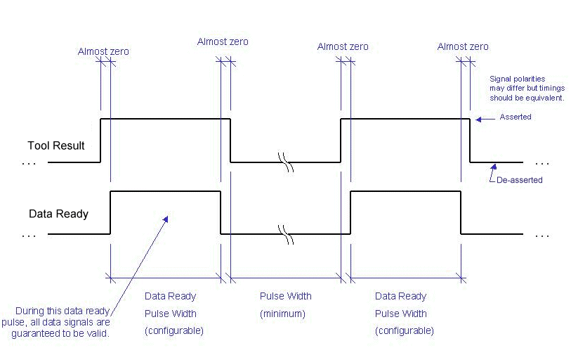
As you configure your QuickBuild application to accept an input signal or generate an output signal, you must select the polarity the line must use to indicate the signal is present. Some signals require the discrete line switch from a Low to High or High to Low state, as illustrated in the following figure:
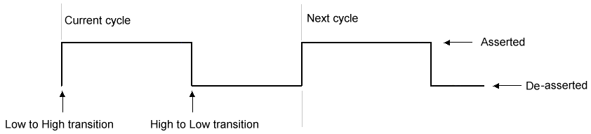
The cycle time, or pulse width, and the choice of which transition you want to use to identify the signal can depend on the external equipment communicating with your QuickBuild application.
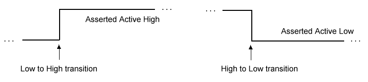
Other discrete signals require an active line state to indicate their presence, as illustrated in the following figure:
Each input signal you want to accept or output signal you want to transmit can be described by the following parameters:
- Line: The specific discrete I/O line on your output hardware
- Usage: Some lines are bidirectional so you must specify each line as an output line or an input line explicitly.
- Owner: Each signal belongs to a specific Job or to the entire QuickBuild application.
- Field: The specific signal type
- Pulse Width: The length of an outgoing pulse signal
- Polarity: The transition from Low to High or High to Low, or the active line state of High or Low
- Description: Your description of the outgoing signal
A QuickBuild application can generate any of the output signals listed in the following table:
| Signal Type | Description |
System Heartbeat | A System Heartbeat is a square wave signal used by various programmable logic controllers (PLCs) in many production environments. A QuickBuild application, regardless of how many jobs it contains, can only generate one System Heartbeat. QuickBuild generates a configured System Hearbeat signal any time the application is Online. See the section Online and Offline for more information. When the application is Offline, it does not generate a System Heartbeat. Be aware of the following usage notes regarding a System Heartbeat:
|
Pulsed Signals | Your QuickBuild application can send a variety of pulsed signals, configured in milliseconds, to indicate the following job events which occur during the vision processing cycle:
|
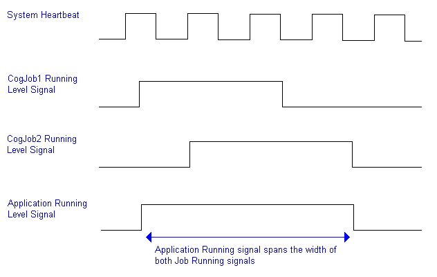
Level Signals | Your QuickBuild application can generate different types of level signals to indicate the current status of a particular Job or the application as a whole:
|
Tool Properties | QuickBuild can send the Accept/Warning/Reject/Error result or the True/False result of any tool within any job. For example you might transmit the Result status for a specific QuickBuild job, or just the True/False result of a single expression within a Results Analysis tool. When you configure an output signal to carry a tool property, QuickBuild will assert the output line when the tool property matches the property you configured. For example, if the property is False at the time you configure the output line, QuickBuild will only assert the output signal when the same tool property is False each time the Job runs. |
A QuickBuild application can respond to a variety of input signals. QuickBuild does not enforce a minimum time period that an input signal must be asserted in order to be recognized, but it must be asserted long enough for QuickBuild to recognize the change of state in the input line. As you develop and test your application, you might choose to mirror any input signal with its corresponding output signal in order to verify that the input signal has sufficient duration and level to trigger the desired event. For example, the outgoing System Heartbeat is active anytime QuickBuild is Online. If you want to confirm that your QuickBuild application received an input signal to go Online, you can configure a System Heartbeat and then monitor its output line to ensure the application acknowledges the signal to go Online.
In general, a Cognex frame grabber can recognize a change of state for a span of 1 millisecond. If you are using a Measurement Computing board to generate an input signal, the signal should be held in the desired state for double the specified polling period. Refer to your Measurement Computing documentation for details on the recommended polling time.
A QuickBuild application can respond to any of the following input signals:
| Signal Type | Description |
Online | An Online signal switches the QuickBuild application from Offline to Online, where it can respond to all input signals and generate any output signals it has been configured to send. See the section Online and Offline for more information. The Online signal performs the same function as the Online option from the Configuration menu or the Online button on the tool bar:  Be aware of the following usage notes regarding an Online signal:
|
Emergency Stop | An Emergency Stop signal stops all running Jobs and switches QuickBuild to Offline status. The QuickBuild application discards any result data currently stored in the I/O queue. Use an Emergency Stop signal to block all output signals in a production environment where you might need to prevent equipment from receiving a signal such as Move Part signal or the Reject result of a tool property. Be aware of the following usage notes regarding the Emergency Stop signal:
|
Run Once | A Run Once signal can be issued to the entire QuickBuild application to run all the Jobs it contains once, or it can be targeted at a single Job within the application. A Run Once signal performs the same function as the Run Once button:  Be aware of the following usage notes regarding the Run Once signal:
|
Run Continuously | A Run Continuous signal can be issued to the entire QuickBuild application to run all the Jobs it contains continuously, or it can be targeted at a single Job within the application. Use the Run Continuous signal when you want to acquire and inspect images in a continuous manner, which is typical of a deployed application. The Run Continuous signal performs the same function as the Run Continuous button: 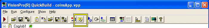 Be aware of the following usage notes regarding the Run Continuous signal:
|
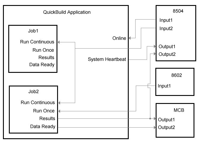
The following diagram illustrates how multiple Jobs in a QuickBuild application can use the discrete I/O signals from a combination of Cognex frame grabbers and Measurement Computing boards:
The following table describes several use cases for Discrete I/O and the I/O signals you can use.
| Task | Discrete I/O Signals |
Signal all Jobs in a QuickBuild application to run continuously |
|
Collect a tool result |
|
Stop the QuickBuild application from running all Jobs |
|
Disable all output signals but allow the QuickBuild application to continue running |
|
Stop the QuickBuild application from running all Jobs and disable all output signals from QuickBuild, include the signals to activate strobe lights |
|