This topic contains the following sections.
Whenever you use an image processing tool to produce a new image by processing the pixels in an input image, the image processing tool is responsible for establishing the coordinate space tree of the output image. Image processing tools generally modify the image's coordinate space tree so that the relationship between pixel space ("#") and root space reflects the effect of the image processing operation. For example, if you use the Gaussian Sampling tool to subsample and smooth an image, the resulting output image will have its space tree adjusted so that the location of features in the smoothed and sampled image is the same as their locations in the input image.
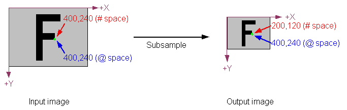
The following figure shows how this works. In the input image, pixel space (# space) and root space (@ space) are identical. The indicated point has the same location in both spaces. After subsampling the image (with a sampling factor of 2 in both the X- and Y-direction), the output image has one fourth as many pixels as the input image. Accordingly, the same location (shown in green) has changed in pixel space. In root space, however, the location has not changed, because the Gaussian Sampling tool updated the output image's root space to reflect the effect of the image processing operation. This automatic change to root space means that when you use pattern location tools, or specify regions, or perform any other operations using the image's root space, the locations you specify will correspond to the locations in the original image.
The following table provides a summary of the types of adjustments made by various types of image processing tools that take a single input image. For detailed information about a particular tool, refer to the documentation for that tool.
| Operation | Sample Input | Output |
Affine Transformations If you use the CogAffineTransformTool or if you use the CogRegionModeConstants region mode with the Cognex one-image or two-image tool, the image processing tool sets the output image's root space to reflect the transformation between the supplied input region (an affine rectangle) and the output image. | 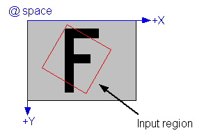 | 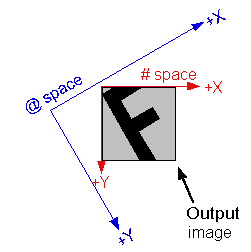 |
Image Flip or Rotate. If you use the one-image tool to flip or rotate the input image, the root space of the output image will reflect the flip or rotation. |  | 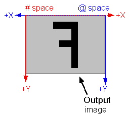 |
| The CogCopyRegionTool behaves like an affine transformation (described above). The output image's root space reflects the transformation between the input image's root space and the region being copied. | 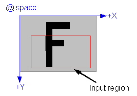 | 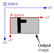 |
Kernel-based Image Processing Tools Most tools that perform image processing operations by successively applying a kernel to the pixels in an input image produce an output image that is smaller than the input image. The size reduction depends on the size of the kernel. For a 3x3 kernel (the most common size), the image is reduced in size by 2 pixels in both the X- and Y-direction. The root space in such an output image is automatically adjusted to compensate for this effect. The Gaussian Sampling tool is an exception to this rule. That tool synthetically generates the "missing" pixels, so its output image is the same size as its input image. |  | 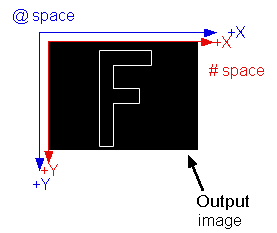 |
By default, image processing tools that take two input images (such as the CogIPTwoImageAddTool) operate in exactly the same way as the single-image tools described in the preceding section. The root space of the output image is based on the composition of the root space of the input image together with any transformation implied by the input region for the first image. The coordinate space tree of the second image is essentially ignored, except for computing the image alignment.
In some cases, however, you may wish to preserve information from both input images in the output image's coordinate space tree. You do this by specifying CogIPTwoImageSpaceTreeModeConstants or CogIPTwoImageSpaceTreeModeConstants for the tool's SpaceTreeMode property. When you do this, the two-image tool merges the space tree from the second image with the first image's space tree. It does this by creating a new space, with a name that you specify using the MergedSpaceTreeName property, then attaching the second image's @ space to this new space using an identity transformation (I). The newly created space reflects the alignment of the second image with respect to the first image. This merging allows you to continue to refer to features in the combined image using coordinates from either of the input images' space trees.
The following figure shows how this merge is done:
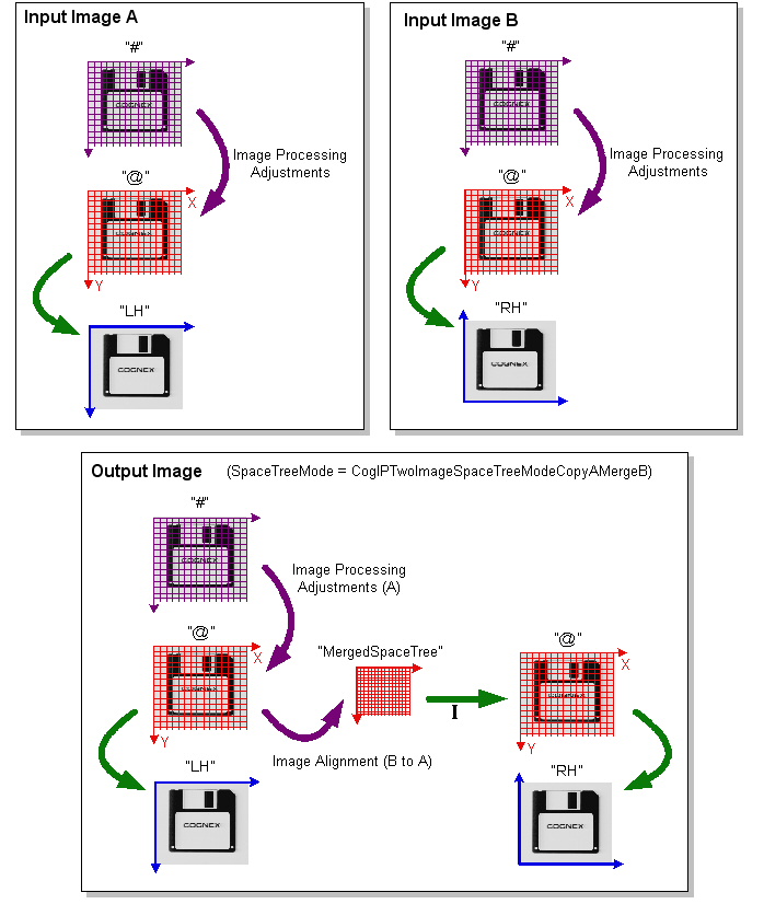
Note that in the case of the merged part of the space tree, the second space named "@" is not a true root space. If you set the selected space to "@", it will refer to the first "@" space. To refer to spaces in the merged part of the tree, you must use names like "@\MergedSpaceTree\@\RH".