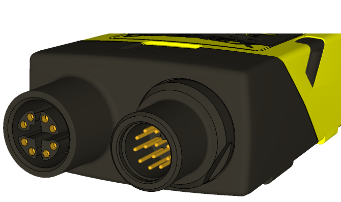
Connectors and Indicators
|
|
|---|---|
| Connector | Function |
| Ethernet connector (left) | Connects the Ethernet cable and supplies power1 to the vision sensor. For more information, refer to Ethernet Cable Specifications. |
| Power, I/O and RS-232 connector (right) |
Connects the Breakout cable, which provides connections to an external power supply2, the acquisition trigger input, general-purpose inputs, high-speed outputs, and RS-232 serial communications. For more information, refer to Breakout Cable Specifications. Alternately, this connector is used to attach the I/O Module cable to a compatible In-Sight I/O module, which adds general-purpose discrete I/O. For more information, refer to I/O Module Cable Specifications. |
|
||
|---|---|---|
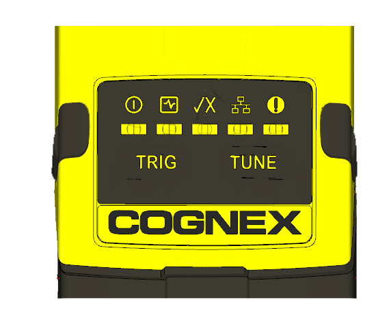
| Indicator | Function | |

|
Power LED | The green LED illuminates to indicate that the vision sensor is powered on. |

|
Status LED |
Yellow when active. User-configurable (LED 5 Yellow). |

|
Pass/Fail LED | Green (pass) or red (fail) when active. User configurable (LED 4 Green/LED 4 Red). |

|
Network LED | The yellow LED flashes to indicate network activity. |

|
Error LED | Red when active. |

|
Trigger button |
Manually triggers an image acquisition when the vision sensor is either:
|

|
Tune button | Unsupported. |