3D-L4000 Series Vision System Wizard – Sensor Settings
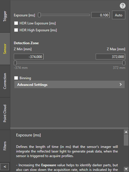
The 3D-L4000 Series Acquisition Wizard contains the sensor properties of the 3D-L4000 series vision systems on its Sensor tab. These settings allow you to set the exposure, sensitivity or HDR settings of the acquisition, and fine-tune the sensor's Z-axis detection zone as well. You can modify these settings both before and after field correction is performed.
| Setting | Description |
| Exposure |
Sets the exposure time for every profile acquisition (in ms), that is the time that the sensor's imager will use to acquire each raw image to find a laser profile. The value range is between 0.011 – 25, and the default value is 0.1. Tip:
|
| HDR |
The HDR Low and High Exposure sliders allow you to configure multiple exposures to generate peak data if the target surface has varying reflectance, and using only the Exposure setting results in under- or oversaturated areas. Enabling both HDR Low and High Exposure lets you acquire image data with 3 different exposure settings.
Note: The acquisition rate (indicated with Max Profile Rate) is affected by the number of exposures and their configured values as well. Therefore, enable HDR only if the results of a single exposure are insufficient.
|
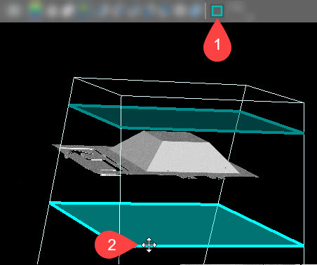
| Detection Zone |
Sets the lower and upper bounds of the vision system's measurement range (in mm) in which shapes and surfaces are detected, and image data is generated. Use the sliders to manually adjust the size, or enter a specific value. The Z min value (specifying the lower bound of the working section) cannot be higher than the Z max value, and likewise, the Z max value (specifying the upper bound of the working section) cannot be lower than the Z min value. Tip:
|
| Binning | Enables 2x2 binning that treats 2x2 pixel data as one pixel on the raw image. If this setting is enabled, it halves the resolution of the acquired profiles, resulting in a coarser point cloud, but in faster Exposure values and a higher Max Profile Rate. |
| Advanced Settings | |
| Selected Peak |
Defines how the sensor will select the peak data for height calculation:
Tip:
Set the Top or Bottom settings to reduce possible false peaks if you are sure that the nearest/farthest peak in the intensity image column is the correct surface to use. This is useful if the profile contains strong but false peaks. For example, if you are measuring the height of a semi-transparent cover on top of an opaque object, the acquisition would contain a weak peak from the cover and a stronger peak from the object beneath the cover. However, since you want to measure the cover, and not the object under it, you should use the Top setting. |
| Sensitivity |
Sets the laser detection sensitivity, that is a lower threshold for laser line intensity detection. The value range is 0 – 1, and the default value is 0.9. Tip:
|
| Peak Width Threshold |
When enabled, it specifies an upper width threshold (in pixels) for laser line detection. As such, this setting can reduce the chance of detecting false peaks by removing spikes that are commonly characterized by wide laser lines due to multiple reflections. The value range is 1 – 100, and the default value is 5. Note: Peak data generated out of a laser line with a width higher than the specified value will be filtered out. All other peak data will be kept.
|