3D-L4000Series Vision System Wizard – Point Cloud Settings

The 3D-L4000 Series Acquisition Wizard contains additional point cloud configuration settings for 3D-L4000 series vision systems on its Point Cloud tab. You can modify these settings before field correction is finalized.

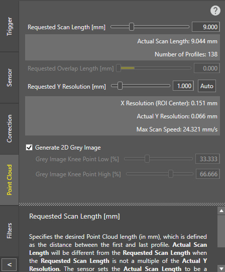
Requested Scan Length (mm)

Specifies the desired point cloud length, that is the distance between the first and last profile acquisition (in mm). The actual scan length and the number of profiles accumulated with the current settings are shown below the setting slider, and is updated real-time as the setting's value is modified. The value range is 0 – 5000, and the default value is 9.

Note:
  • The Actual Scan Length will be different from the Requested Scan Length if it is not a multiple of the Actual Y Resolution. The system will set the Actual Scan Length to the multiple of the Actual Y Resolution that is closest and larger than the Requested Scan Length.
  • This setting assumes good field correction. Incorrect Motion Speed or Encoder Resolution values will negatively impact this setting.
Requested Overlap Length (mm)

Specifies the length (in mm) at which the consecutive profile acquisitions can overlap when Trigger Source is set to Continuous. The default value is 0, meaning that no acquisition overlaps are allowed.

Note:
  • The Actual Scan Length becomes different from the Requested Scan Length, if the Actual Scan Length is not a multiple of the Requested Overlap Length. The vision system sets the Actual Scan Length value to the minimum multiple of the Requested Overlap Length which is larger than the Requested Scan Length.

    For example, you define 10 mm for Requested Overlap Length.

    If your Requested Scan Length is 92 mm, the Actual Scan Length becomes 100 mm because 100 mm is the minimum multiple of the Requested Overlap Length which is larger than the Requested Scan Length.

  • The maximum allowable value of Actual Overlap Length is 50% of the value of Actual Scan Length.
  • If you specify a larger Requested Overlap Length value, the Actual Scan Length value automatically adjusts.
Requested Y Resolution (mm)

Specifies the desired distance (in mm) between consecutive profiles in the motion direction. The value range is 0.001 – 100, and the default value is 1.

Note:
  • When configuring the Y Resolution, consider that sometimes, the selected resolution value cannot actually be set by the system. This can occur because of 3 reasons:
    • If encoder-based acquisition is used, the Requested Y Resolution must be a multiple of the encoder resolution. If this is not the case, then the Actual Y Resolution will be modified by the system to be a multiple of the Encoder Resolution that is closest to and smaller than the Requested Y Resolution.
    • If time-based acquisition is used, the configured resolution may not be achievable if the sensor cannot acquire profiles fast enough to reach the requested resolution.
    • The vision system can only acquire a maximum number of profiles. If the combination of the requested scan length and the requested resolution requires more profiles than the maximum allowed value, then the Y resolution will be adjusted accordingly.

  • The 3D-L4000 Series Acquisition Wizard returns an error if the Requested Y Resolution is smaller than the Encoder Resolution. This is because the vision system cannot acquire fast enough to reach the Requested Y Resolution.
Tip:
  • You can set the Requested Y Resolution equal to the X Resolution at the center of the current Region of Interest (ROI). To do so, click Auto.
  • You can also modify this property on the spreadsheet with the ApplyAcquisitionSettings function.
Generate 2D Grey Image

Enables generating 2D greyscale images during acquisition along with the point cloud. The image is generated based on the intensity of each pixel.

Tip:
  • Enable this setting only if you need 2D images as well for your vision application, as 2D image generation increases acquisition latency.
  • You can also enable or disable this property on the spreadsheet with the ApplyAcquisitionSettings function.
Grey Image Knee Point Low

Specifies the lower percentage of the greyscale image knee point when 2 exposures are used. Knee points allow you to define how to combine the intensities of multiple expositions into a single grey intensity image. When using a single HDR exposure, a value lower than 50% means that the intensity from peaks extracted on the higher HDR exposition will be mapped in range 0-127, and the intensity from the peaks extracted on the lower exposure will be mapped in range of 128–255.

Note: This setting is available only if at least one HDR exposure slider is enabled in the Sensor tab.
Grey Image Knee Point High

Specifies the upper percentage of the greyscale image knee point when 3 exposures are used. Knee points allow you to define how to combine the intensities of multiple expositions into a single grey intensity image. When using 2 HDR exposures, a higher value of 66% means that the intensity from the peaks extracted on the lower HDR exposition will be mapped in range 169–255.

Note: This setting is available only if both HDR exposure sliders are enabled in the Sensor tab.