CalibrateGrid
Utilizing a user-configurable calibration grid pattern, CalibrateGrid creates a 2D transformation to convert between pixel and real-world coordinate systems. CalibrateGrid also accounts for linear, non-linear and lens distortion.
About CalibrateGrid
CalibrateGrid computes a 2D transformation between the set of points identified by the vertices of a checkerboard calibration grid pattern. During analysis, CalibrateGrid finds the pixel locations of the grid cell intersections, and then maps them back onto a model of the grid pattern.
In addition, CalibrateGrid uses a reference to a set of calibration points and a lens distortion model to compute a transformation mapping between image and real-world coordinates.
You can configure the following with the CalibrateGrid:
- The type of calibration grid pattern to be used.
- The spacing of the calibration grid pattern.
- The type of real-world, physical measurement units.
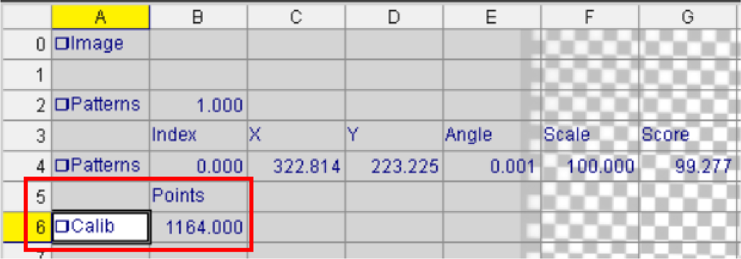
Optionally, you can print a calibration plate grid. For more information, see Printing the Calibration Pattern Using the Print Grid Dialog. Once the image is acquired, CalibrateGrid automatically identifies as many feature points as possible. As soon as you press the Calibration button, CalibrateGrid begins to compute the calibration and reports a calibration point based on the spacing of the feature points.
After the calibration is performed, the CalibrateGrid cell stores the calibration data. This allows you to copy the CalibrateGrid function from one job and paste to another, or export and import as an external file using Export Cell/Import Cell. It is possible to have a different calibration for each job, as well as multiple calibrations in a single job, if necessary. Other functions that use Calibrate functions as arguments can reference the CalibrateGrid data structure.
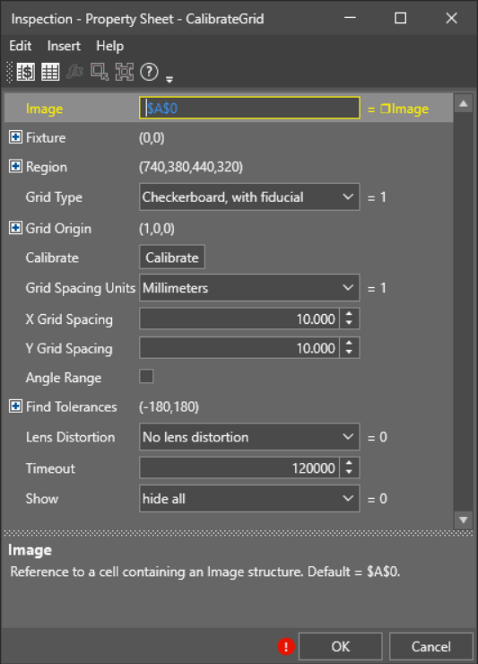
| Parameter | Description | ||||||||||
|---|---|---|---|---|---|---|---|---|---|---|---|
| Image | This argument must reference a spreadsheet
cell that contains a valid Image data structure. By default, the cell references , containing the Image data structure |
||||||||||
| Fixture |
Defines the Region of Interest (ROI) relative to a Fixture input or the output of the image coordinate system for the Vision Tools function. Setting the ROI relative to a Fixture ensures that if the Fixture is rotated or translated, the ROI is rotated or translated in relation to the Fixture. Note: 2D projections use real world units but fixturing with 2D tools requires input in pixel values. When using a 2D projection from a 3D point cloud as a Fixture, convert the real world units to pixel values using the TransWorldToPixel function.
The default setting is (0,0,0), the top leftmost corner of the image.
|
||||||||||
| Region |
Also known as the Region of Interest (ROI), specifies the region of the image that undergoes analysis. Double-click on the Region parameter to create an Interactive Graphics Mode that you can transform and rotate. Select this parameter and press the Maximize Region button on the Job Edit toolbar of the property sheet to automatically stretch the region to cover the entire image.
|
||||||||||
|
Grid Type |
Specifies the type of calibration pattern that is used to construct the calibration:
|
||||||||||
|
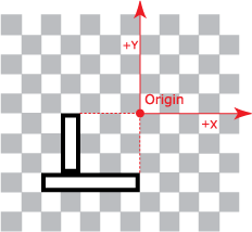
Grid Origin |
Specifies the origin point of the grid.
Note: The Grid Origin parameters are only editable when you choose the Checkerboard, no fiducial for the Grid Type. If you chose Checkerboard, no fiducial, it allows you to manually pick one of the points to be the origin.
|
||||||||||
| Calibrate | CalibrateGrid event trigger. | ||||||||||
|
Grid Spacing Units |
Specifies the real-world measurement units that the calibration is based upon. The default unit is millimeters. You can choose from the following units:
|
||||||||||
| X Grid Spacing | The actual measurement of the calibration grid pattern spacing along the X-axis. | ||||||||||
| Y Grid Spacing | The actual measurement of the calibration grid pattern spacing along the Y-axis. | ||||||||||
| Angle Range |
The start and stop angle range used to search for the grid.
Tip: Restricting angle range can speed up point extraction when the relative orientation between grid and camera is well known.
|
||||||||||
| Find Tolerances |
Check the Angle Range parameter to enable the Find Tolerances parameter and restrict the angle range used to search for the grid. The default setting is unchecked. |
||||||||||
| Lens Distortion |
The linear or non-linear lens distortion model to use in mapping real-world to image coordinates.
|
||||||||||
| Timeout |
Specifies a length of time in milliseconds to allow the CalibrateGrid function to run. Function execution stops when the time out has been exceeded. The minimum value is 0, the maximum is 9999999. The default value is 120000. Note: Timeout is used to as a fail safe to cause potentially very long running processes to terminate once the timeout has been exceeded. Timeout is not exact as execution may run a few seconds over the specified time.
|
||||||||||
| Show |
Specifies the display mode for CalibrateGrid graphical overlays on top of the image.
|
|
Returns |
A Calib data structure containing the coefficients that define the transformation between the two coordinate systems. |
-
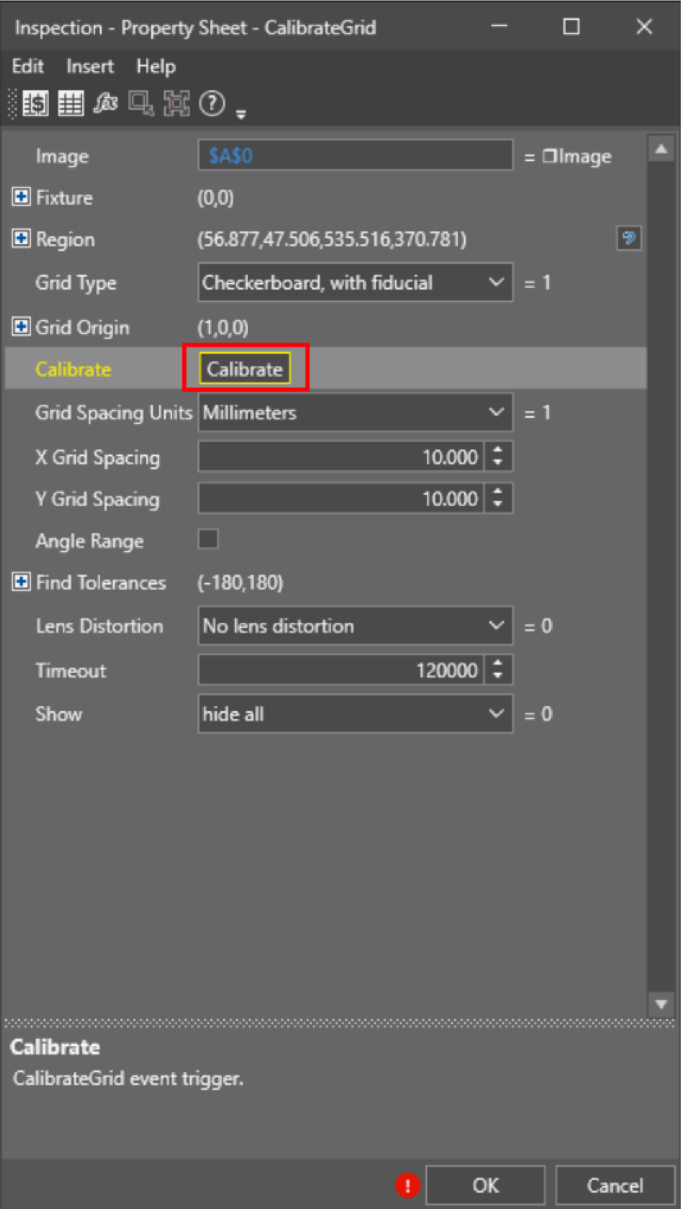
Drag and drop the CalibrateGrid tool to your Spreadsheet.
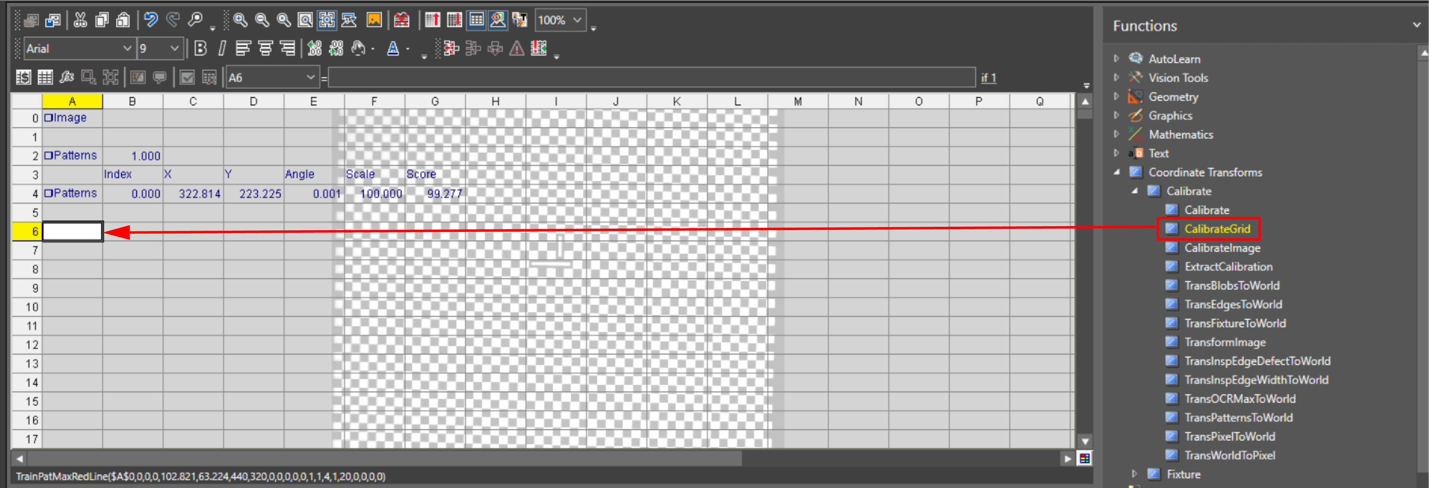
The property sheet appears.
-
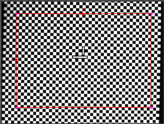
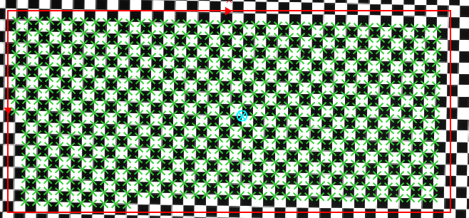
Specify the Region of Interest (ROI) by double-clicking the Region parameter. Select the region by dragging the red lines of the ROI. When finished, press enter or click the Accept Changes.
- Specify the Grid Type. In this case, the checkerboard with fiducial is chosen.
- Specify the Grid Units, which are the real-world measurement units that the real-world coordinates are based upon.
-
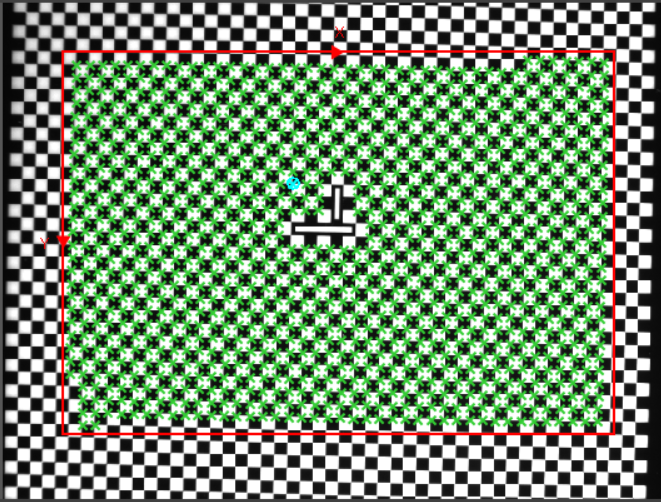
Click Calibrate to trigger the calibration.
When the calibration is finished, the calibrated points appear inside the ROI.
-
Click OK. You receive a Calib data structure.
-
Drag and drop the CalibrateGrid tool to your Spreadsheet.
The property sheet appears.
-
Specify the Region of Interest (ROI) by double-clicking the Region parameter. Select the region by dragging the red lines of the ROI. When finished, press Enter or click the Accept Changes.
- Specify the Grid Type. In this case, the checkerboard, no fiducial is chosen.
-
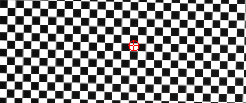
Decide whether you want to manually determine the Grid Origin.
- If you do not want to manually determine the origin point, leave the checkbox checked in at the Center checkbox.
-
If you want to manually determine the origin point, uncheck the Center checkbox. Double-click the X button and drag the origin point where you want to be. Press Enter, when finished.
-
Click Calibrate to trigger the calibration.
When the calibration is finished, the calibrated points appear inside the ROI.
-
Click OK. You receive a Calib data structure.