Creating a Filmstrip
When constructing the HMI for your application, adding a filmstrip to display acquired images and the overall results of the inspection can be done by combining a Shift Register, VisionPro Display and Script Block.
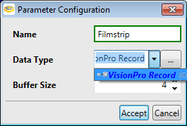
- Add a Shift Register, and configure it to act as the filmstrip.
Name the Shift Register "Filmstrip", set the Data Type to VisionPro Record and the Buffer Size to the number of images that you want to display (for this example, the Buffer Size was set to 4).
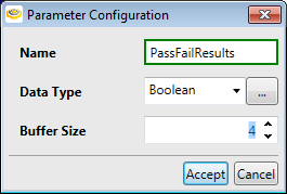
- Add a second Shift Register, and configure it to record the pass/fail results of the images being displayed.
Name the Shift Register "PassFailResults", set the Data Type to Boolean and the Buffer Size to the number of results to be displayed (again, the Buffer Size for this example was set to 4).
- Add a Script Block to the Task, which will be used to compile the images and results.
- In the Script Definition Editor, name the script "CreateFilmstrip" and add two arguments: the first, named "Image" with a Data Type of VisionPro Record, and the second, named "Result" with the Data Type set to Boolean.
In the Script Editor, add the following script:
$Components.Filmstrip.Add(Image);
$Components.PassFailResults.Add(Result);
This will create two input pins on the Script Block.
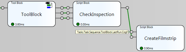
The first input pin should be assigned to the output of the tool outputting the image, by either configuring a Tool Block to provide an output pin, or assigning the pin to a tag. The second input pin should be assigned to a block that qualifies the result as either pass or fail. In this example, a Script Block is used to qualify the results of the inspection, using the following script:
if (CenterX > 273)
return true;
else
return false;
if (CenterY > 277)
return true;
else
return false;
if (Radius > 78)
return true;
else
return false;
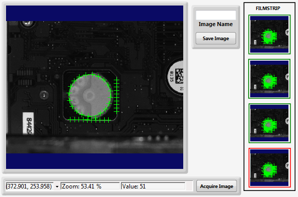
- On the Page, add and configure the VisionPro Display elements that will be used to display the images for the filmstrip, and the Rectangle Page Graphics elements that will be used to indicate the pass/fail status.
- For the first VisionPro Display, set the Subject property to Item0 of the Filmstrip Shift Register: $Components.Filmstrip.Item0.
Add the other VisionPro Display elements, and set their Subject property to the rest of the Items of the Filmstrip Shift Register (e.g. $Components.Filmstrip.Item1, $Components.Filmstrip.Item2 and $Components.Filmstrip.Item3).
Tip: To save time and effort, right-click the first VisionPro Display element, select Copy, and then Paste the other elements. Go to each pasted VisionPro Display and set the Subject property accordingly.To display the Pass/Fail results related to the image and its inspection, add a Rectangle element and configure it to surround the VisionPro Display.
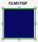
Set the Color property of the Rectangle to Item0 of the PassFailResults Shift Register: $Components.PassFailResults.Item0.
When the Tag Selector dialog appears, enable the Show All Types checkbox to navigate to the PassFailResults Shift Register tags.
Note: The Type Mismatch dialog will appear after making the selection; ignore the mismatch and Press Yes to continue.Before closing the Expression Builder, create an association between the colors, with Green being Pass, and Red being Fail.
Note: For more information about creating the association, see the Binding Associations topic.Add the other Rectangle elements to the VisionPro Display elements.
Tip: To save time and effort, right-click the first Rectangle element, select Copy, and then Paste the other elements. Go to each pasted Rectangle and set the Color property accordingly. You will not need to adjust the Association.
-
Enter Test Mode and acquire images to verify whether or not the expected images and results appear.
Note: See the Display an Acquired Image for more information about configuring the Page to display and acquire images.